T-bar for suspended ceiling with heat dissipation system for LED lighting

a technology of led lighting and heat dissipation system, which is applied in the field of t-bars, can solve the problems of inconvenient installation, inconvenient installation, and inability to meet the needs of lighting, and achieve the effects of minimizing energy utilization, convenient and inexpensive installation, and optimizing lighting performan

Active Publication Date: 2012-05-15
JLC TECH IP LLC
View PDF2 Cites 42 Cited by
  • Summary
  • Abstract
  • Description
  • Claims
  • Application Information

AI Technical Summary

Benefits of technology

[0007]With this invention, a T-bar is provided for a dropped ceiling which is configured to transfer heat effectively away from T-bar and ceiling mounted light sources and other heat sources, and into a space above a dropped ceiling. The T-bar can have any of a variety of different general cross-sections including a spine and a rest shelf at a lower end of the spine. Anchors are provided at terminal ends of the T-bar for attachment of ends of the T-bar within a conventional dropped ceiling system. For instance, the T-bar anchors can attach to adjacent T-bars or other supports in the forming of an entire lattice of T-bars within an existing conventional dropped ceiling system. A lower portion of the T-bar and beneath the rest shelf includes a light housing which can contain a lighting module therein. In a preferred form of this invention this lighting module includes at least one light emitting diode (LED) light source therein. An upper heat sink is coupled to the spine. This upper heat sink includes fins with gaps between the fins to enhance a rate of heat transfer between the heat sink and air adjacent the upper heat sink and above the ceiling tiles.
[0008]The T-bar preferably also includes a lower heat sink in the form of fins extending from the rest shelf. Preferably these fins include an outer fin and short fins closer to the spine than the outer fin. The outer fin is preferably longer than the short fins. In this way, an air pathway is provided from gaps between the fins of the lower heat sink and a ceiling tile resting upon the outer fin, for effective natural convection heat transfer away from the lower heat sink. The lower heat sink and light housing, as well as the spine and upper heat sink are preferably each formed together from a unitary mass of material to maximize heat transfer from the LED or other heat source to the heat sinks and then to the air within the space above the dropped ceiling. The entire T-bar is formed of a material having a higher than average thermal conductivity so that efficient heat transfer away from the LED or other heat source is accomplished.
[0009]A power supply for the LED is configured to be attachable to the upper heat sink so that a complete assembly for powering the LED lighting within the T-bar is suspended from the T-bar within the dropped ceiling system. By placing the lighting suspended from a lower surface of the T-bar, gaps within the T-bar lattice of the dropped ceiling system that would otherwise contain lighting can contain additional ceiling tiles to further enhance a resistance to heat transfer through the dropped ceiling to enhance an overall efficiency of the space conditioned by the HVAC system. Also, the aesthetic appearance of the ceiling can be enhanced by eliminating breaks in the ceiling for large prior art lighting bays. For instance, an entire ceiling of uniform ceiling panels can be provided, including the option to provide unique regular patterns, such as alternating colors in a checkered pattern.OBJECTS OF THE INVENTION

Problems solved by technology

One major factor in energy consumption of a building is the efficiency with which the space is heated and cooled.
Space above the dropped ceiling typically has an undesirably hot or cold temperature compared to the conditioned space below.
An additional source of power consumption within a building is the power consumed by lighting.
Not only does lighting within a building directly affect energy consumption due to the power utilized to drive the light sources, but also lighting often generates significant heat within the conditioned space which then must be transferred from the space when the space is experiencing an unacceptably high temperature.
LED lighting also typically has a longer life than other lighting technologies.
One problem that is generated by utilization of LED lightings in particular, is that while a relatively low amount of heat is generated by the LED lighting, this heat is concentrated in a particularly small space directly adjacent the LED electronics required to generate the light.

Method used


Image

  • T-bar for suspended ceiling with heat dissipation system for LED lighting
  • T-bar for suspended ceiling with heat dissipation system for LED lighting
  • T-bar for suspended ceiling with heat dissipation system for LED lighting

Examples


Embodiment Construction

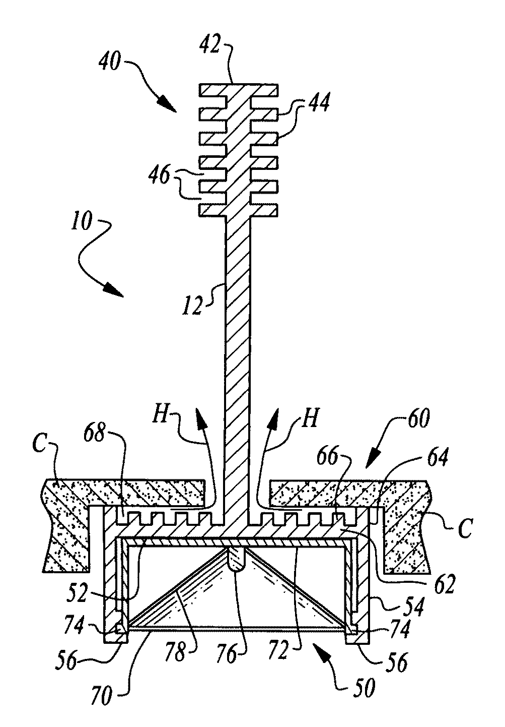
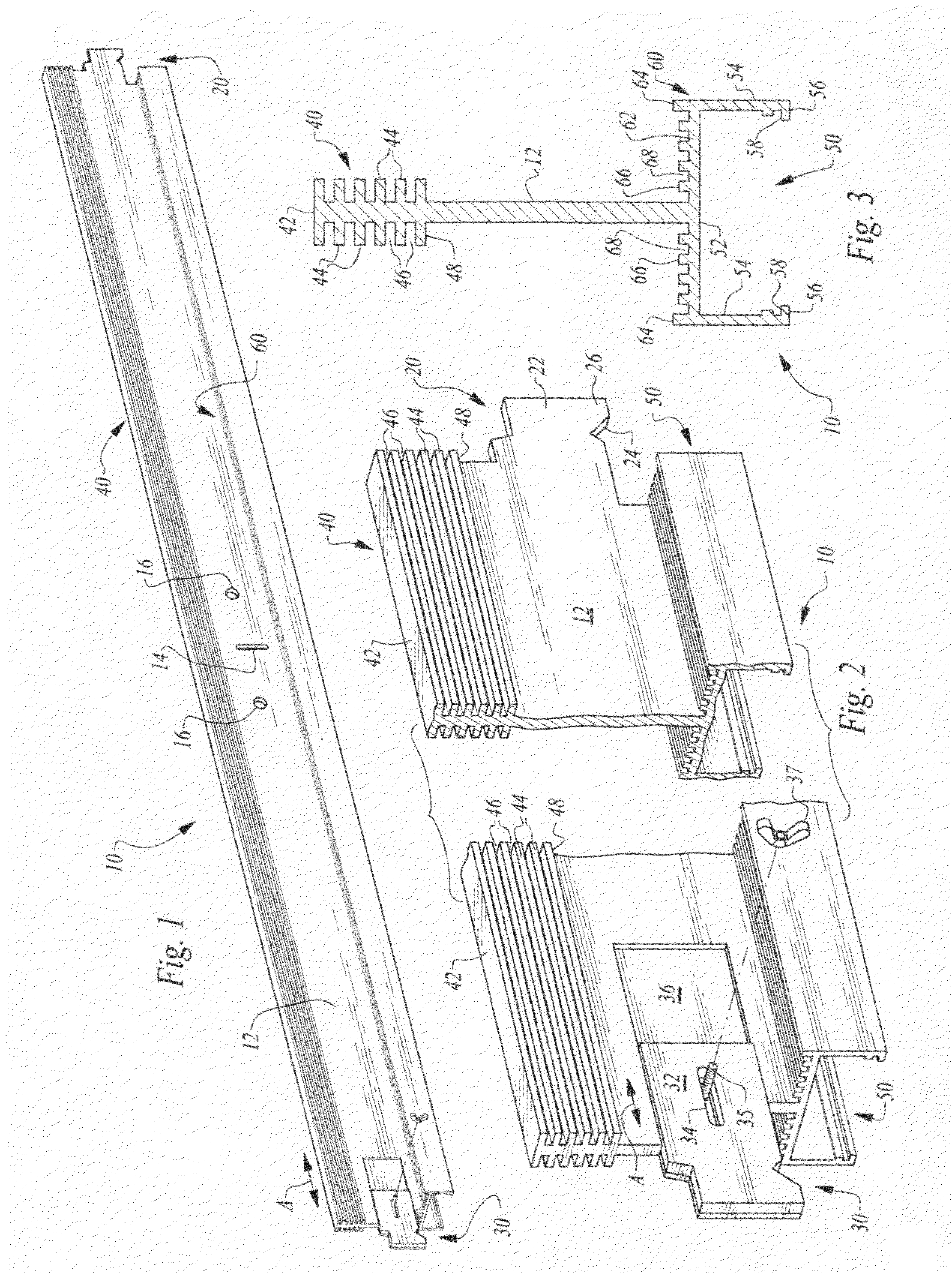
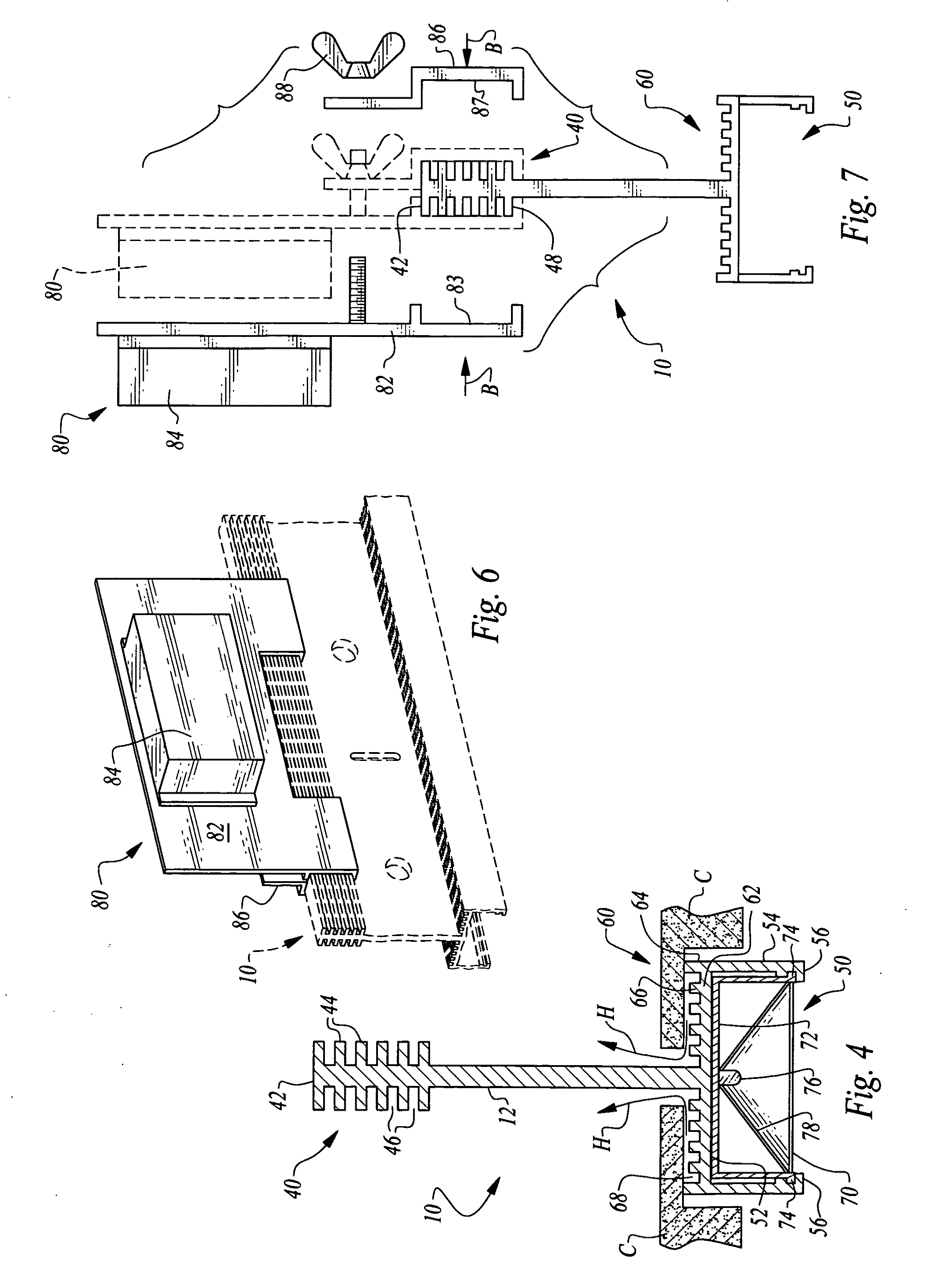
[0029]Referring to the drawings, wherein like reference numerals represent like parts throughout the various drawing figures, reference numeral 10 is directed to a T-bar (FIG. 1) forming a portion of a dropped ceiling system (FIG. 5) with the T-bar including a lighting module 70 (FIGS. 4, 5, 8 and 9) coupled to a lower end of the T-bar 10 for providing lighting in a space below the dropped ceiling system. The T-bar 10 includes heat dissipating structures including an upper heat sink 40 and lower heat sink 60 in this preferred embodiment for dissipating heat from the lighting module 70 or other heat sources adjacent the T-bar 10.

[0030]In essence, and with particular reference to FIGS. 1-3, basic details of the T-bar 10 and associated features of this invention are described, according to this most preferred embodiment. The T-bar 10 is an elongate rigid structure extending between terminal ends and preferably having a substantially constant contour between the two terminal ends of the...


PUM


Abstract

The T-bar includes an elongate rigid spine extending between terminal ends including either a fixed anchor or adjustable anchor for attachment to adjacent T-bars or other supports. An upper heat sink is provided on an upper portion of the spine to enhance heat transfer from the T-bar to air surrounding upper portions of the T-bar. A light housing is provided on a lower portion of the T-bar which is configured to support a lighting module therein, such as a light emitting diode (LED) light. A lower heat sink is provided above this light housing and integrated into a rest shelf which supports ceiling tiles adjacent the T-bar. A power supply is provided which can be removably attached to the T-bar and provide appropriately conditioned power for the lighting module.

Description

FIELD OF THE INVENTION[0001]The following invention relates to T-bars for use in supporting ceiling tiles within a suspended ceiling. More particularly, this invention relates to T-bars which include lighting supported therefrom, and particularly LED lighting, with the T-bar configured to include a heat sink for dissipating heat generated by the light source.BACKGROUND OF THE INVENTION[0002]A common form of surface finish for ceilings, especially within commercial construction is the “dropped ceiling.” With a dropped ceiling a lattice of T-bars is suspended at a height desired for the ceiling. Ceiling tiles are provided which have a size and shape matching gaps in this lattice of T-bars. These ceiling tiles are placed within these gaps to fill these gaps between the T-bars. The T-bars generally have a shape with a vertically extending spine portion and a horizontally extending rest shelf so that the T-bar is generally in the form of an upside down “T.”[0003]Lighting for interior bui...

Claims


Application Information

Patent Timeline
Patent Type & Authority Patents(United States)
IPC IPC(8): F21S8/00
CPCE04B9/006E04B9/067F21V29/004F21V33/006F24F3/056F21V23/023F21V23/026F21S2/005F21S4/008F21S8/04F21V33/0088F21Y2101/02F21Y2105/001F21S4/28F21Y2105/10F21Y2115/10E04B9/064F21V29/767F21V29/763F21S8/026F21S8/02F21V29/503F21V29/74F21S8/043
Inventor PORCIATTI, SILVIO
Owner JLC TECH IP LLC
Why Eureka
Try Eureka