
Apparatus for positive feeding from a preconditioner

a technology of preconditioner and apparatus, which is applied in the direction of mixer accessories, mixers, mixing, etc., can solve the problems of significant operational and/or contamination problems, affecting the desirable continuous flow of material, and incorporating airborne contaminants into the material

Active Publication Date: 2012-05-15
WENGER MFG LLC
View PDF22 Cites 35 Cited by
  • Summary
  • Abstract
  • Description
  • Claims
  • Application Information

AI Technical Summary

Benefits of technology

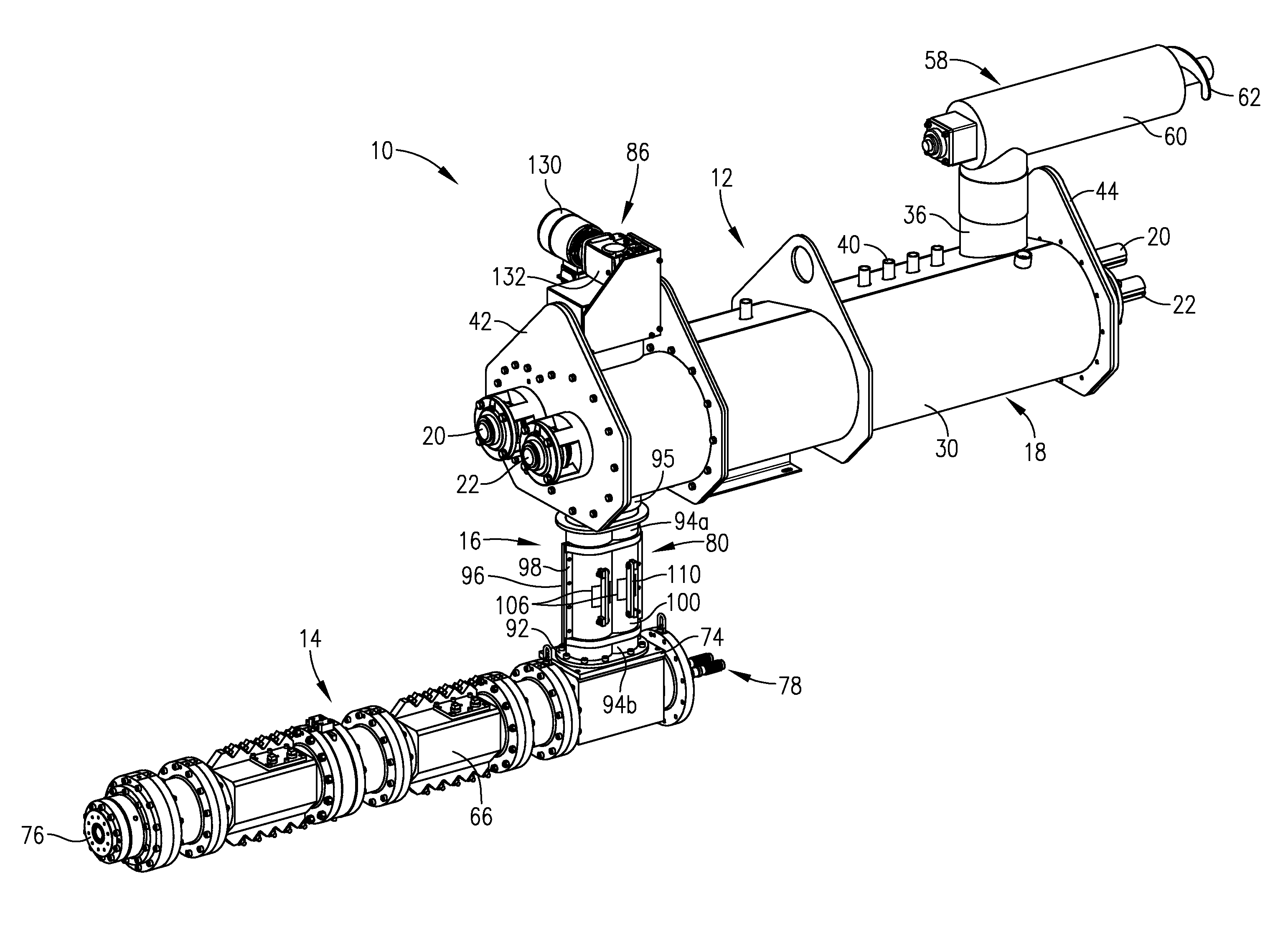
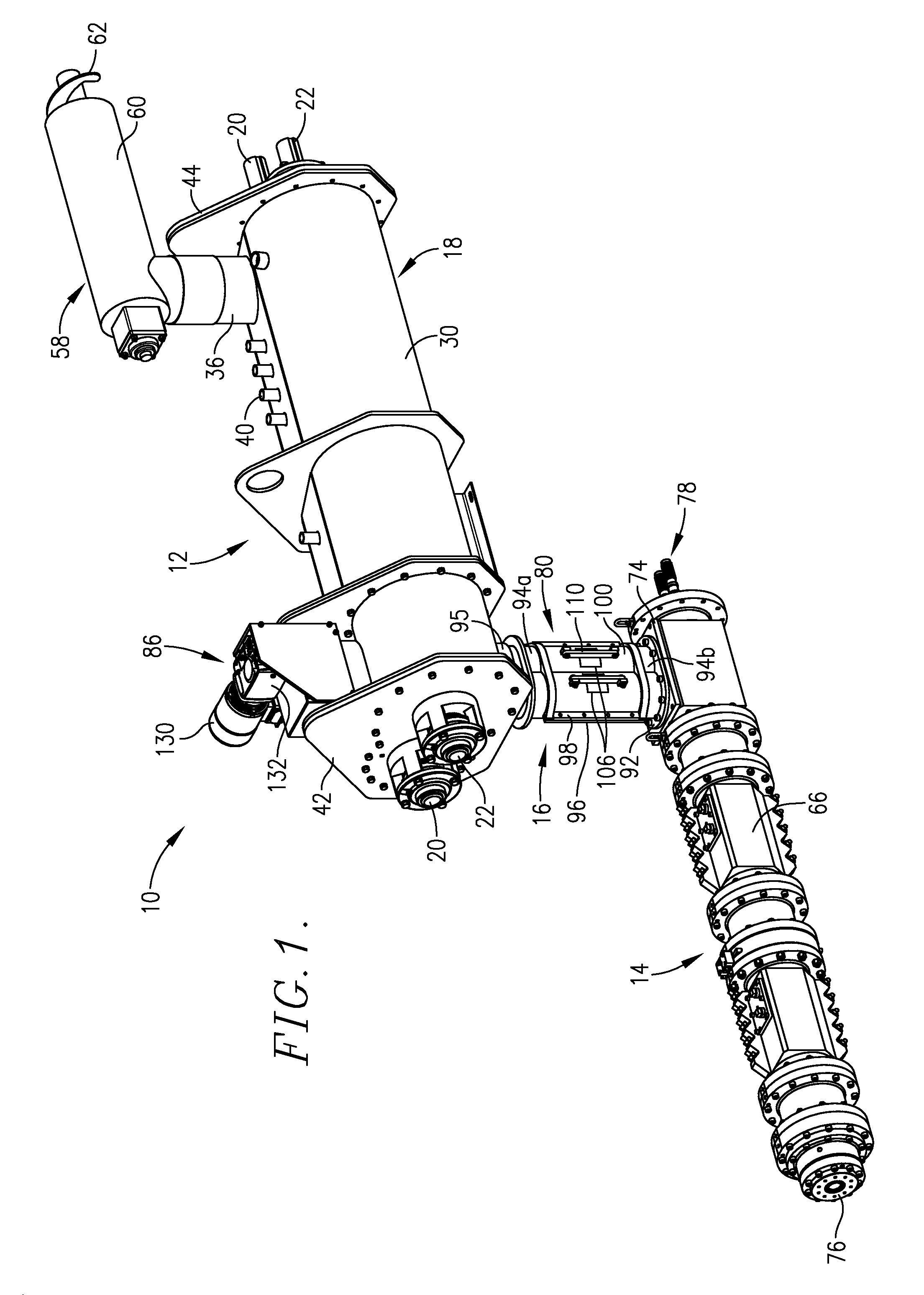
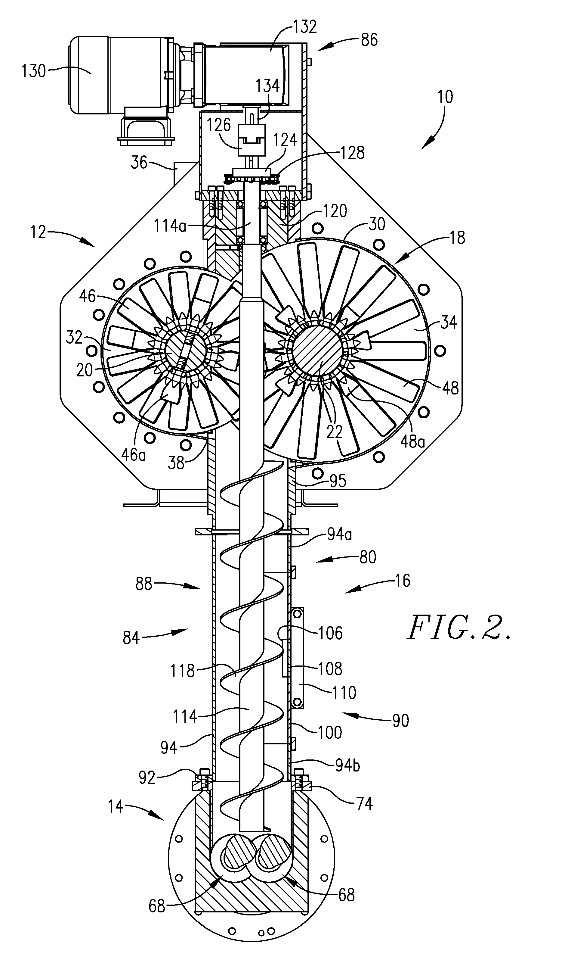
[0009]The present invention overcomes the problems outlined above, and provides an elongated, upright feeder screw assembly designed to be located between a preconditioner outlet and an extruder inlet in order to provide positive transport of the preconditioned material substantially throughout the length of the assembly. Generally speaking, the feeder screw assembly has an elongated upright housing presenting an upper inlet end and a lower outlet end, with a pair of juxtaposed feeder elements within the housing, each including an upright shaft supporting helical flighting along the length thereof, with a motor operably coupled with the shafts for axial rotation thereof. In preferred forms, the shafts extend through the preconditioner vessel to a point within the extruder inlet closely adjacent the extruder screw(s). Advantageously, the feeder screw housing is designed to closely mate with the preconditioner outlet and extruder inlet to create a substantially closed passageway there between. This reduces the possibility of atmospheric contamination of the material being processed, and moreover makes it possible to pressure both the preconditioner and the feeder screw housing.

Problems solved by technology

The use of downspouts or transitions between the preconditioner outlet and extruder inlet can create significant operational and / or contamination problems.
For example, owing to the fact that the preconditioner and downspout are substantially at atmospheric pressure, there is a possibility that airborne contaminants are incorporated into the material during processing.
Furthermore, because the flow of material in the downspouts relies on gravity and is not positively conveyed, the material can clog within the downspout, thereby disrupting the desirable continuous flow of material between the preconditioner and the extruder.
However, the system of the '453 patent still relies on gravitational flow from the discharge feeder to the inlet of the downstream extruder.

Method used


Image

  • Apparatus for positive feeding from a preconditioner
  • Apparatus for positive feeding from a preconditioner
  • Apparatus for positive feeding from a preconditioner

Examples


Embodiment Construction

[0016]Turning now to the figures, a processing apparatus 10 in accordance with the invention broadly includes a preconditioner 12, an extruder 14, and a feeder screw assembly 16 interconnecting the preconditioner 12 and extruder 14. The apparatus 10 is especially designed for the processing of feed or food products, typically containing quantities of protein, starch, and fat. A particular utility of the apparatus 10 is in the production of relatively dense aquatic feeds, such as shrimp feeds.

[0017]In more detail, the preconditioner 12 is of the type described in U.S. Pat. No. 7,674,492, incorporated by reference herein in its entirety. Broadly, the preconditioner 12 includes an elongated mixing vessel 18 with a pair of parallel, elongated, axially-extending mixing shafts 20 and 22 within and extending along the length of vessel 18. The shafts 20, 22 are operably coupled with individual variable drive devices 24 and 26 (FIG. 5), the latter in turn connected with digital control devic...


PUM


Abstract

An improved screw feeder assembly is provided for interconnection between the outlet of a preconditioner and the inlet of an extruder barrel. The assembly includes an upright housing with a pair of elongated shafts equipped with auger flighting within the housing and driven by means of motor. Preferably, the housing is mechanically coupled to the outlet and inlet with the shafts extending through the preconditioner vessel and downwardly to a point within the inlet and closely adjacent the screw(s) within the extruder barrel; the flighting is provided along the length of the housing, from a point closely adjacent the outlet and into the extruder inlet. This provides a positive conveyance of preconditioned material from the outlet to the inlet. Use of the assembly allows maintenance of superatmospheric pressures and temperatures above 212° F. within the preconditioner, which permits more efficient processing.

Description

CROSS-REFERENCE TO RELATED APPLICATION[0001]This application is a continuation of U.S. patent application Ser. No. 13 / 275,787, filed Oct. 18, 2011, which is incorporated herein by reference in its entirety.BACKGROUND OF THE INVENTION[0002]1. Field of the Invention[0003]The present invention is broadly concerned with improved extrusion apparatus generally including a preconditioner and an extruder, with an intermediate feeder screw assembly coupled between the preconditioner outlet and the extruder inlet in order to positively convey material being process from the preconditioner directly into the extruder. More particularly, the invention is concerned with such apparatus and corresponding methods, wherein the feeder screw assembly preferably includes a substantially closed housing with a pair of juxtaposed, intercalated auger conveying screws within the housing having flighting preferably extending from a point closely adjacent the preconditioner outlet and into the extruder inlet.[...

Claims


Application Information

Patent Timeline
IPC IPC(8): B01F7/04
CPCB01F7/001B01F7/00133B01F7/00141B01F7/042B01F15/0289B01F27/0723B01F27/0724B01F27/071B01F27/702B01F35/754551
Inventor WENGER, MARC
Owner WENGER MFG LLC
Learn More