Slow wave structure having offset projections comprised of a metal-dielectric composite stack

a slow wave and composite stack technology, applied in the direction of transit-time effect amplifiers, traveling-wave tubes, coupling devices of transit-tubes, etc., can solve the problems of limiting amplifier power and bandwidth, and conventional wide-band slow wave structures (sws) for amplifying rf waves are not suitable for electron sheet beam configurations

Active Publication Date: 2012-05-15
TELEDYNE DEFENSE ELECTRONICS LLC
View PDF365 Cites 9 Cited by
  • Summary
  • Abstract
  • Description
  • Claims
  • Application Information

AI Technical Summary

Benefits of technology

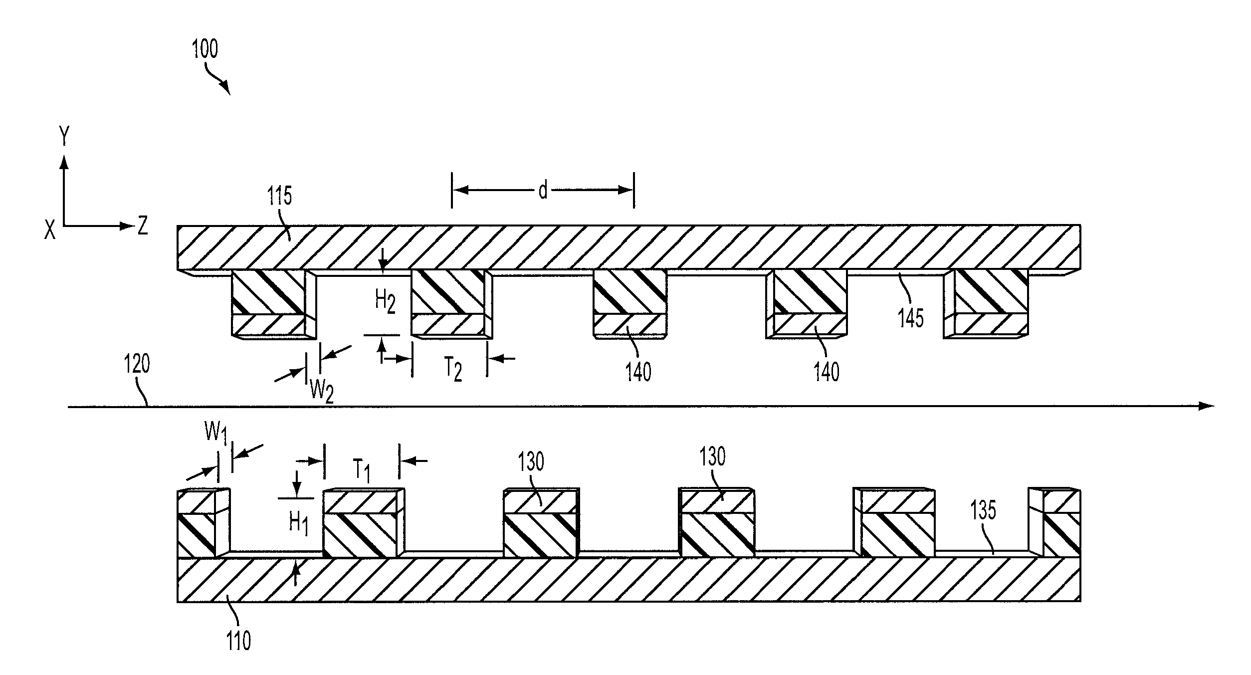
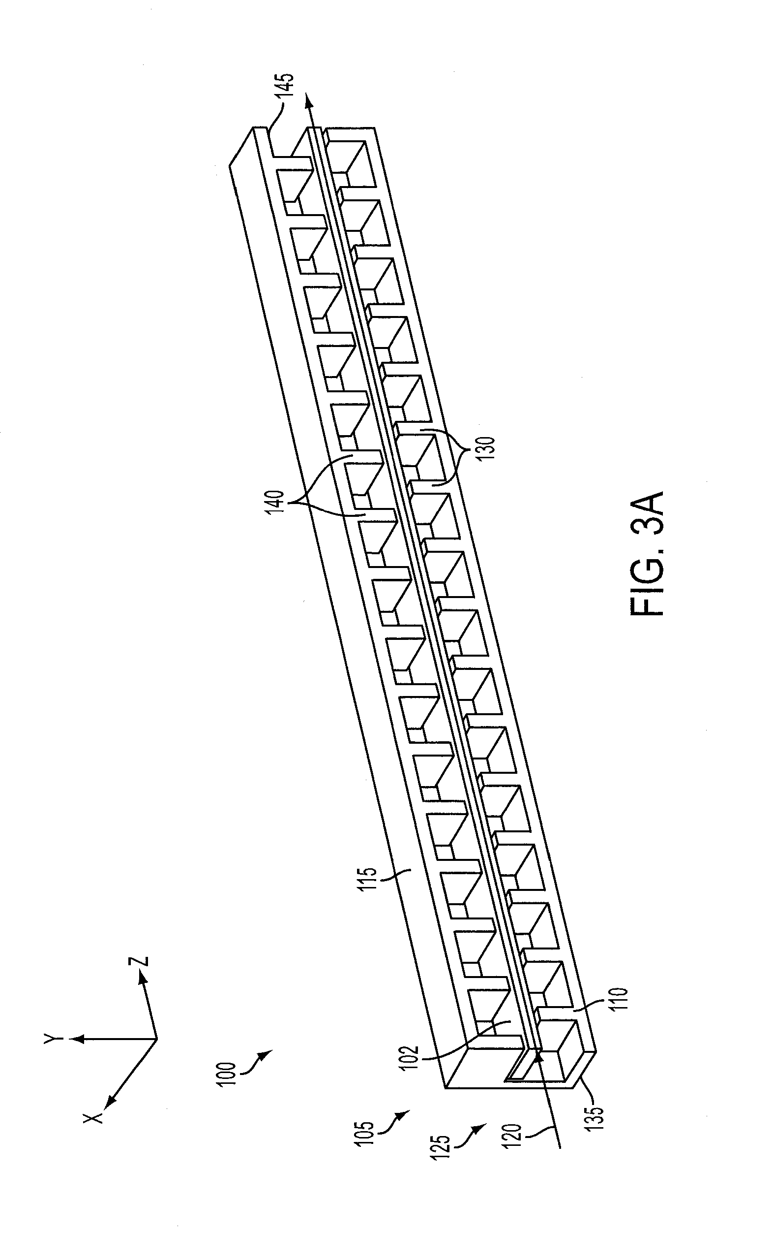
[0008]In another general respect, this application discloses a device including an electron sheet beam source for generating an electron sheet beam, and an amplifier circuit coupled to the electron sheet beam source to receive the electron sheet beam and an RF wave to effect synchronized interaction therebetween. The circuit includes a wave guide having at least a first wall and a second wall opposite the first wall. The first wall and the second wall are connected to define an axis of propagation and a rectangular wave guide cross-section that is normal to the axis of propagation. The circuit further includes a plurality of first projections located on an interior surface of the first wall of the wave guide, the first projections being pitched in a direction of the axis of propagation. The circuit further includes a plurality of second projections located on an interior surface of the second wall of the wave guide, the second projections being pitched in a direction of the axis of propagation. A number of the second projections are located on the interior surface of the second wall in a staggered configuration in a direction of the axis of propagation relative to a number of corresponding first projections located on the interior surface of the first wall.

Problems solved by technology

Conventional vacuum tube microwave power amplifiers that utilize cylindrical electron beam geometries may not be suitable for high frequency and high bandwidth applications.
Therefore, at higher frequency and power, current density may exceed the confinement capability of known magnetic materials, which, in turn, limits amplifier power and bandwidth.
Conventional wide band slow wave structures (SWS) (e.g., a helix SWS) for amplifying RF waves are not suitable for electron sheet beam configurations.

Method used


Image

  • Slow wave structure having offset projections comprised of a metal-dielectric composite stack
  • Slow wave structure having offset projections comprised of a metal-dielectric composite stack
  • Slow wave structure having offset projections comprised of a metal-dielectric composite stack

Examples


Embodiment Construction

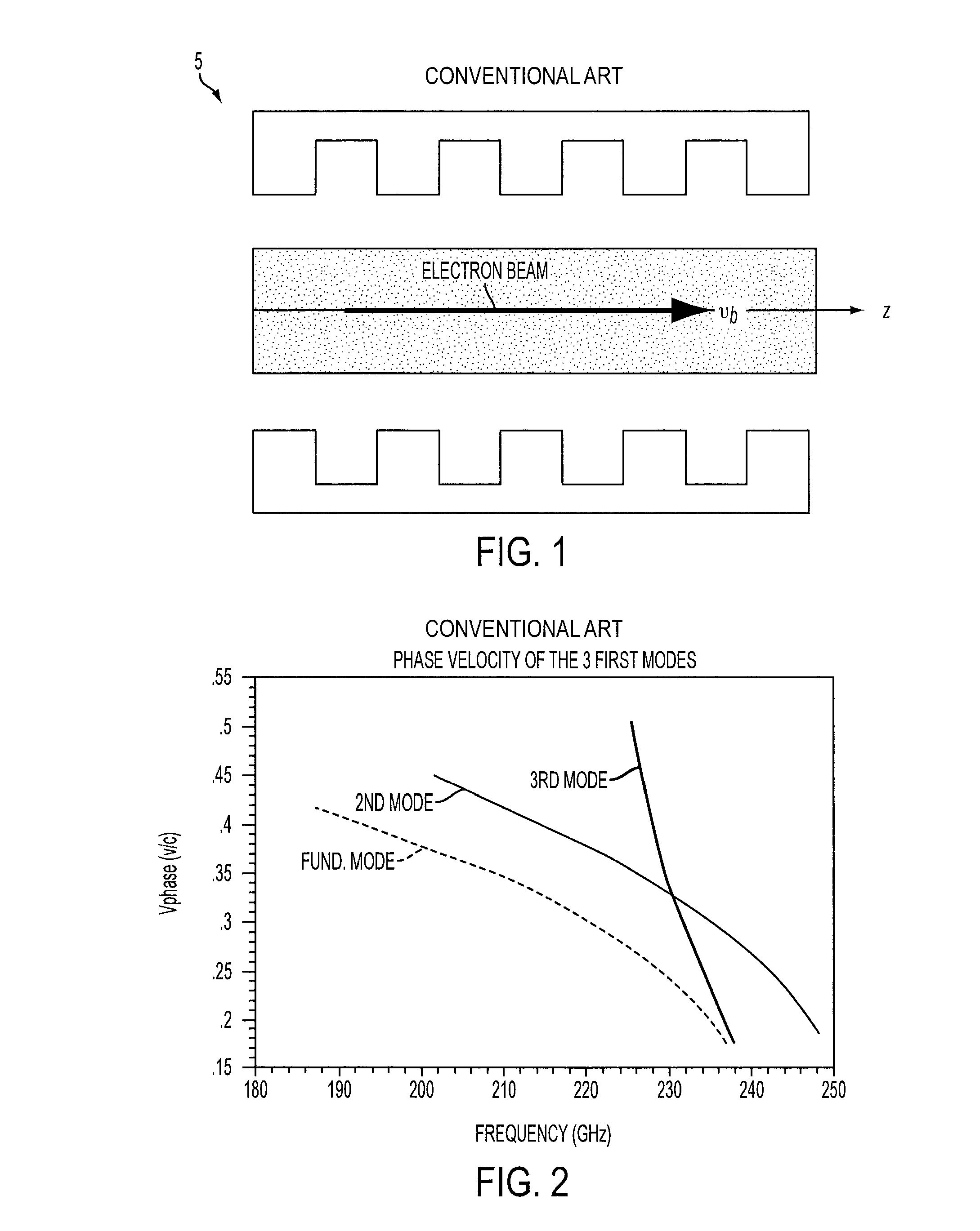
[0022]FIG. 1 is a cross-section side view of a high frequency electron sheet beam SWS in the form of a double metallic aligned vane structure 5, also referred to in the art as a Smith-Purcell structure. FIG. 1 shows an electron beam traveling through a Smith-Purcell structure along an axis z. The electron beam travels through the Smith-Purcell structure at a velocity vb. One drawback of the Smith-Purcell structure 5 is that its fundamental mode is a backward wave mode which may drive an amplifier using this structure into oscillations. Additionally, the axial electric field of the fundamental mode is anti-symmetric in the vertical direction, thus disrupting the electron sheet beam to an extent. Moreover, amplifiers using the Smith-Purcell structure 5 must operate at a relatively high voltage (i.e., high phase velocity) and at a relatively narrow bandwidth due to circuit dispersion. FIG. 2 illustrates a phase velocity {VPhase (v / c)} vs. frequency, in GHz, characteristic of the first ...


PUM


Abstract

A traveling wave amplifier circuit to receive an RF wave and an electron sheet beam and to effect synchronized interaction therebetween. The circuit includes a wave guide having at least a first wall and a second wall opposite the first wall. The first wall and the second wall are connected to define an axis of propagation and a rectangular wave guide cross-section that is normal to the axis of propagation. The circuit further includes a plurality of first projections located on an interior surface of the first wall of the wave guide, the first projections being pitched in a direction of the axis of propagation. The circuit further includes a plurality of second projections located on an interior surface of the second wall of the wave guide, the second projections being pitched in a direction of the axis of propagation. A number of the second projections are located on the interior surface of the second wall in a staggered configuration in a direction of the axis of propagation relative to a number of corresponding first projections located on the interior surface of the first wall.

Description

CROSS REFERENCE TO RELATED APPLICATION[0001]This application claims priority from U.S. Provisional patent application Ser. No. 61 / 047,048 filed Apr. 22, 2008, the disclosure of which is incorporated herein by reference.TECHNICAL FIELD[0002]This application is directed generally and in various embodiments to slow wave structures (SWS) and electron sheet beam-based amplifiers including same.BACKGROUND[0003]Amplifiers come in many forms and are used in many applications. For example, amplifiers may be used with digital or analog signals in communications systems such as, for example, wireless telecommunications and satellite communications systems. Generally, amplifiers are either semiconductor-based or vacuum tube-based. Because electrons can travel at a higher velocity in a vacuum than in a semiconductor, vacuum tube amplifiers may be fabricated from structures that are larger relative to those of semiconductor-based devices but that have comparable transit times. Larger structures p...

Claims


Application Information

Patent Timeline
Patent Type & Authority Patents(United States)
IPC IPC(8): H01J23/38H01J25/34
CPCH01P3/123H03F3/58
Inventor GOREN, YEHUDA G.LALLY, PHILIP M.
Owner TELEDYNE DEFENSE ELECTRONICS LLC
Why Eureka
Try Eureka