Apparatus and method for performing hardware and software co-verification testing

a technology of hardware and software, applied in the field of apparatus and method for performing hardware and software co-verification testing, can solve the problems of significant time elapse before the test software, no sequencing solution, and inability to execute arm assembler instructions, etc., and achieve the effect of flexible and efficient techniqu

Active Publication Date: 2012-05-15
ARM LTD
View PDF3 Cites 8 Cited by
  • Summary
  • Abstract
  • Description
  • Claims
  • Application Information

AI Technical Summary

Benefits of technology

[0021]In accordance with the present invention, a debugger signal interface controller is provided which is operable to interface with a debugger used to control the operation of a processing unit associated with the system under verification. A test manager is then arranged to send test controlling messages to the debugger signal interface controller, and to other signal interface controllers coupled to the system under verification, identifying test actions to be performed by those interface controllers. With regard to the debugger signal interface controller, this enables the test manager to cause the debugger signal interface controller to perform one or more test actions such that at least one of one or more stimulus signals and one or more response signals are passed between the debugger and the debugger signal interface controller during performance of the sequence of verification tests, this allowing the test manager to control the operation of the processing unit via the debugger signal interface controller and the debugger in order to co-ordinate the execution of the software routines with the sequence of verification tests.
[0023]In accordance with the present invention, the debugger is controlled by the test manager via the debugger signal interface controller, which provides a very flexible and efficient technique for controlling operation of a processing unit coupled to that debugger.
[0031]However, in an alternative embodiment, the debugger signal interface controller is operable to perform a predetermined test action in order to cause a breakpoint to be set by the debugger which is triggered when the processing unit performs said update of the status data. The ability for a debugger to set a breakpoint is a standard feature of many debuggers. In accordance with this embodiment of the present invention, this feature is used to improve the efficiency of the process, since it is no longer necessary to periodically interrupt the operation of the processing unit in order to determine whether the execution of the software routine has completed. Further, this can improve the accuracy of the verification process, since it avoids any risk that the periodic interruption of the processing unit during execution of the software routine might affect the successful operation or otherwise of that software routine.
[0033]Whilst in the above described embodiment a breakpoint mechanism is used for handshaking status information between the software running on the processing unit and the debugger signal interface controller, it will be appreciated that various other mechanisms may be used, for example a watchpoint mechanism may be used. Furthermore, in embodiments where the debugger and its interface to the system under verification support a shared status memory which can be accessed by the debugger signal interface controller whilst the software is running, it will be appreciated that there may be no requirement for such a breakpoint mechanism to be used. Indeed, future ARM debugger implementations may provide hardware support for reading and writing memory whilst software is running on the processor, and in such embodiments no break-point shared data handshaking would be required.
[0035]In one embodiment, the software routines to be executed by the processing unit may be pre-stored in memory, and accordingly for example may be stored in a ROM. However, in an alternative embodiment, at least one of the software routines is written into the memory via the debugger under the control of the debugger signal interface controller. Accordingly, the test manager may issue test controlling messages to the debugger signal interface controller to cause the debugger signal interface controller to perform one or more test actions in order to transfer the instructions making up a software routine into the memory via the debugger. This provides a flexible approach for loading of software into the memory for execution by the processing logic.
[0037]In one embodiment of the present invention, multiple processing units are provided, and a corresponding multiple of debugger signal interface controllers are provided, each debugger signal interface controller communicating with the same debugger to cause their respective test actions to be performed. Accordingly, it can be seen that the technique of embodiments of the present invention is readily expandable to systems where multiple processing units are used, and accordingly provides a very flexible technique for the co-verification of hardware and software.

Problems solved by technology

Up until now however, none of these solutions has been able to address the sequencing and co-ordination of test routines as part of an XVC manager test scenario.
In either case, the above testbench environment cannot execute ARM assembler instructions; neither can it emulate a processors bus activity whilst executing the instruction stream.
If the testbench is running in an RTL simulation environment, some significant time may elapse before the test software is ready to accept RVD-XVC commands.
This is because using interrupts is both intrusive and more difficult to debug.
The drawback here is that test routines cannot be interrupted by the RVD-XVC in mid operation to examine progress etc, but this is not seen to be an important issue at this stage.

Method used


Image

  • Apparatus and method for performing hardware and software co-verification testing
  • Apparatus and method for performing hardware and software co-verification testing
  • Apparatus and method for performing hardware and software co-verification testing

Examples


Embodiment Construction

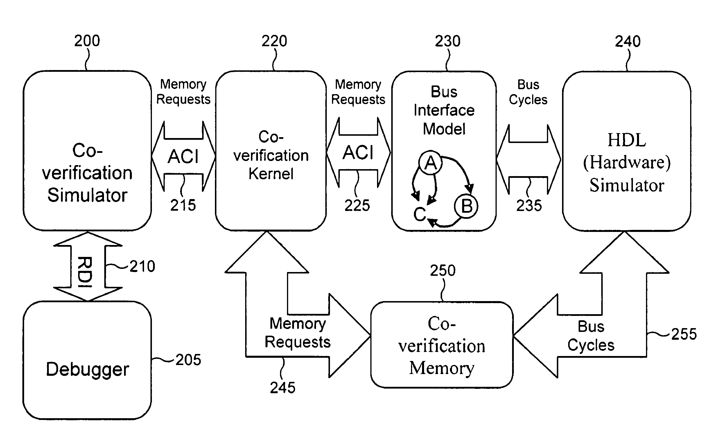
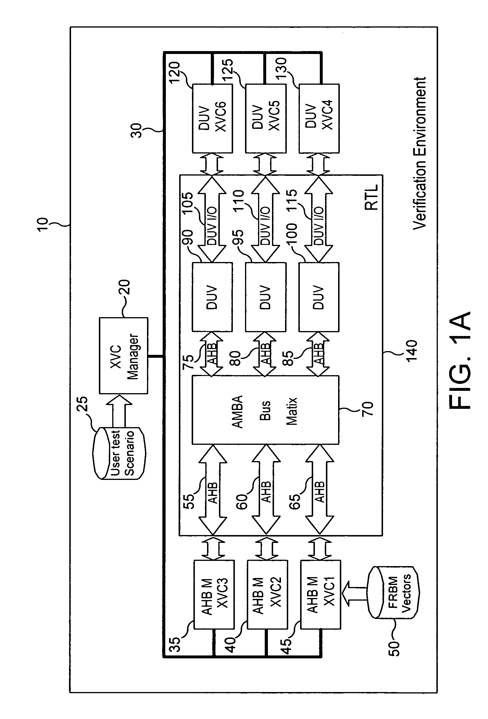
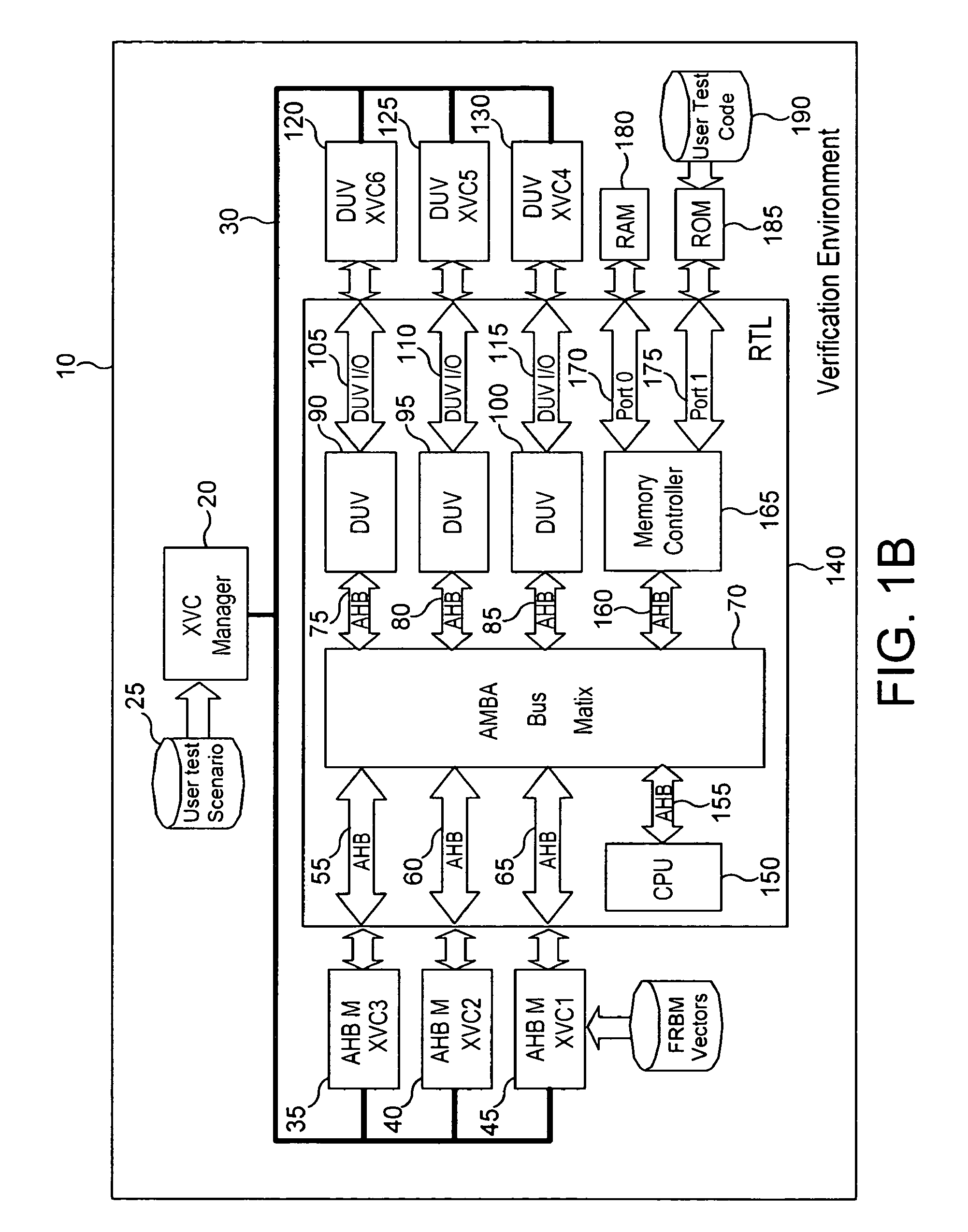
[0060]FIG. 3 is a block diagram illustrating an apparatus for performing hardware and software co-verification in accordance with a first embodiment of the present invention. By comparison with the earlier described prior art of FIG. 1B, it can be seen that the same reference numerals have been used for those elements that are the same as described earlier with reference to FIG. 1B, and those elements operate in the same manner as described earlier with reference to FIG. 1B. By comparison of FIG. 3 with FIG. 1B, it can be seen that the verification environment 10 of the first embodiment of the present invention now additionally includes a debugger 310 and an associated debugger signal interface controller 300 which is coupled to the test manager 20 via path 30. In the particular example illustrated in FIG. 3, the debugger is an ARM RealView Debugger (RVD) and the debugger signal interface controller is accordingly an RVD signal interface controller, also referred to herein as an RVD...


PUM


Abstract

Verification tests perform hardware and software co-verification on a system under verification. Each signal interface controller coupled to the system performs a test action transferring at least one of stimulus signals and response signals between a corresponding portion of the system under verification and the signal interface controller during verification. A debugger controls an associated processing unit that executes software routines. A debugger signal interface controller performs test actions transferring stimulus signals and response signals between the debugger and the debugger signal interface controller during verification. A test manager transfers test controlling messages to these interface controllers identifying the test actions to be performed. As a result, the test manager controls the processing unit via the debugger signal interface controller and the debugger in order to coordinate the execution of the software routines with a sequence of verification tests.

Description

BACKGROUND OF THE INVENTION[0001]1. Field of the Invention[0002]The present invention relates to techniques for performing hardware and software co-verification testing as part of verifying the design of a data processing system.[0003]2. Description of the Prior Art[0004]The ability to effectively and efficiently test and / or validate designs is becoming increasingly important. Typical data processing system designs are rapidly increasing in complexity and furthermore are including circuit blocks designed by a variety of different sources or companies. So-called System-on-Chip (SoC) designs that integrate a large number of functional elements on a single integrated circuit have strong advantages in terms of cost and performance, but require significant amounts of validation and testing before the designs can be reliably released for manufacture. This validation and testing requirement is becoming a bottleneck in getting new systems into the market place. Consequently, measures that c...

Claims


Application Information

Patent Timeline
Patent Type & Authority Patents(United States)
IPC IPC(8): G06F17/50G06F9/455
CPCG06F11/3672
Inventor NIGHTINGALE, ANDREW MARK
Owner ARM LTD
Why Eureka
Try Eureka