Mailing apparatus for powered cards

a technology for mailing apparatus and powered cards, applied in the field of powered, can solve the problems of saving a customer the trouble of visiting a retail location, and achieve the effect of preventing the activation of the activation devi

Inactive Publication Date: 2012-05-22
BRIGHTVOLT INC
View PDF329 Cites 17 Cited by
  • Summary
  • Abstract
  • Description
  • Claims
  • Application Information

AI Technical Summary

Benefits of technology

[0008]In accordance with an embodiment of the present invention, a mailing apparatus is provided for maintaining an electronically powered card in a deactivated state. The apparatus includes a housing having a face panel and two side panels attached to the face panel at opposite sides. The side panels extend from the face panel in a direction generally perpendicular to the face panel. The apparatus further includes an electronically powered card that has an activation device on a surface thereof and an offset mechanism that establishes an offset distance between the electronically powered card and the face panel so that a force exerted upon the face panel is resisted by the face panel and prevented from causing activation of the activation device of the card.
[0010]In accordance with another aspect of the prevent invention, a method of packaging and maintaining an electronically powered card in a deactivated state is provided. In the method, a housing is provided that has a face panel and two side panels attached to opposite sides of the face panel and an electronically powered card is inserted into the housing so that an offset distance is established between the face panel and all activation device located on a surface of the card facing the face panel. The housing with the inserted electronically powered card is mailed. The housing and the card have an interface that establishes the offset distance between the face panel and the activation device during transport so that the activation device is not activated by a force exerted on the face panel in a direction generally perpendicular to the face panel.
[0011]In accordance with another aspect of the prevent invention, a method of packaging and maintaining an electronically powered card in a deactivated state is provided. In the method, a prevention element is adhered onto an electronically powered card. The electronically powered card has an activation device on a surface thereof and the prevention element is disposed adjacent the activation device. The electronically powered device and adhered prevention element is inserted into an envelope or mailing container and the envelope or mailing container is mailed with the electronically powered card and adhered prevention element inserted therein. The prevention element has a thickness sufficient to prevent the activation of the activation device when a force is applied to an envelope or mailing container disposed over the prevention element during transport in a direction generally perpendicular to the activation device.

Problems solved by technology

The convenience of receiving a card through the mail saves a customer the trouble of visiting a retail location to pick up a card.
Powering the cards, however, has introduced difficulties in complying with USPS postal regulations, which dictate that any device powered by dry-cell batteries must have the batteries removed or deactivated to prevent activation of the device in the mail.

Method used


Image

  • Mailing apparatus for powered cards
  • Mailing apparatus for powered cards
  • Mailing apparatus for powered cards

Examples


Embodiment Construction

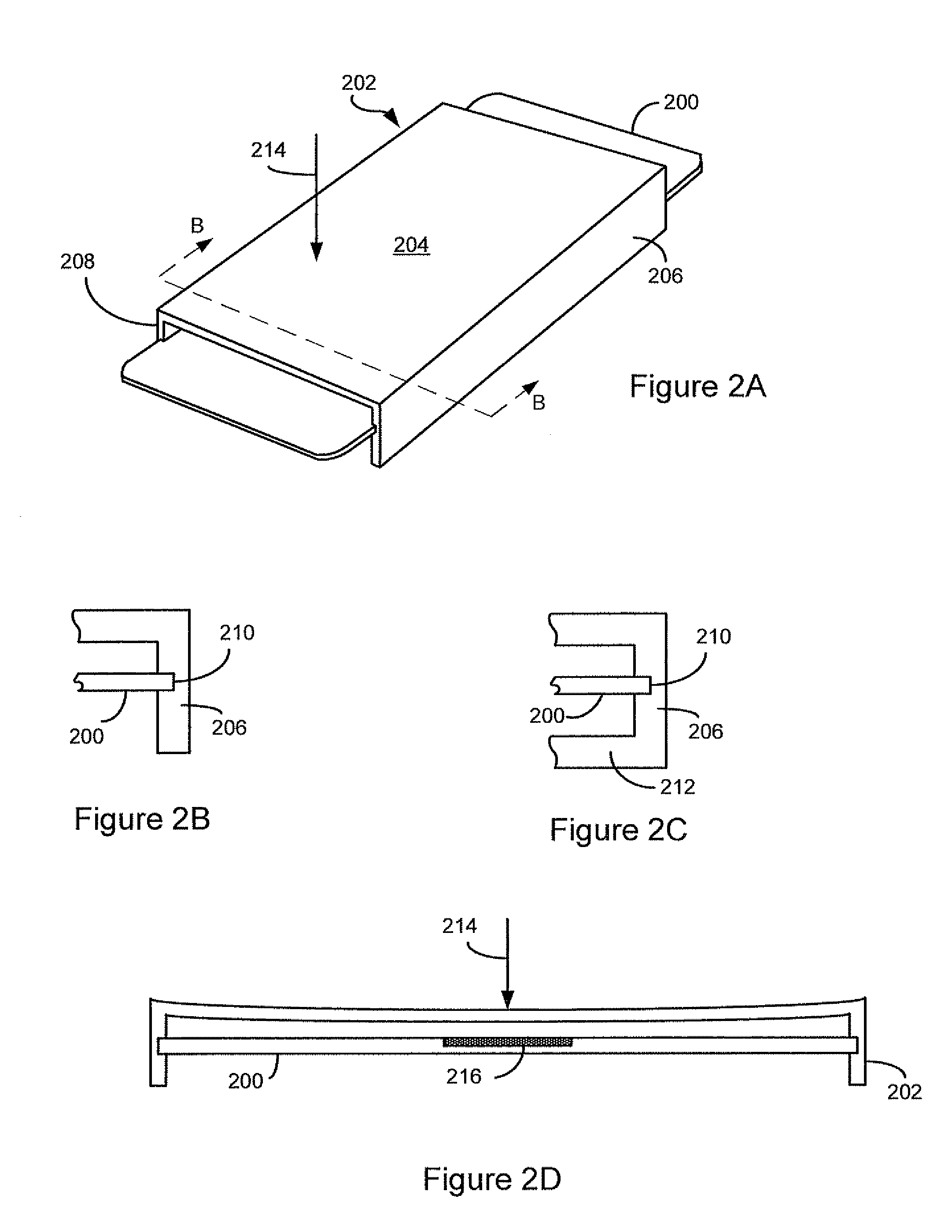
[0028]Embodiments of the present invention provide a mailing apparatus for a powered card. The mailing apparatus prevents activation of the powered card during mailing.

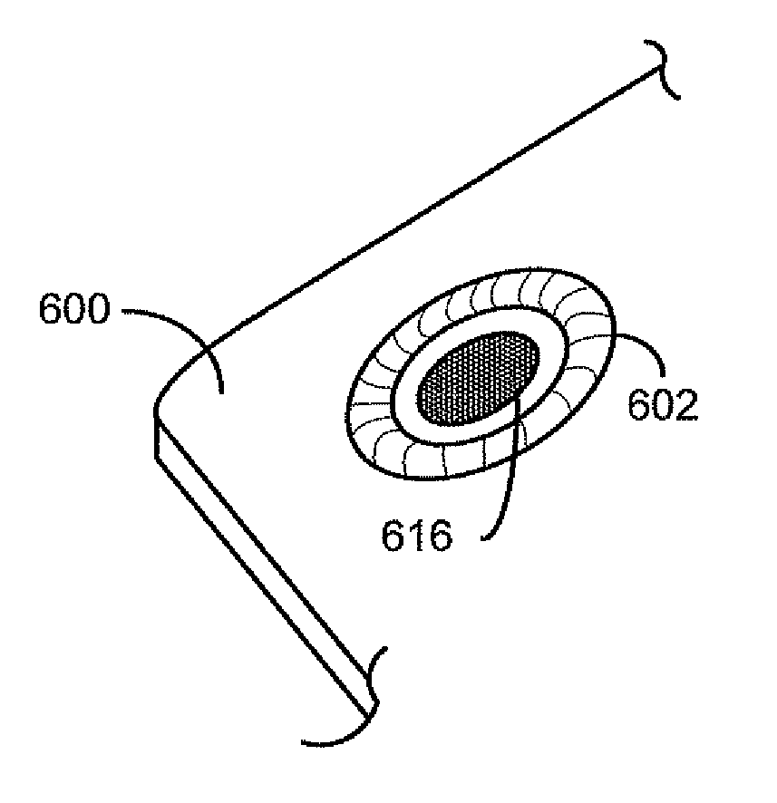
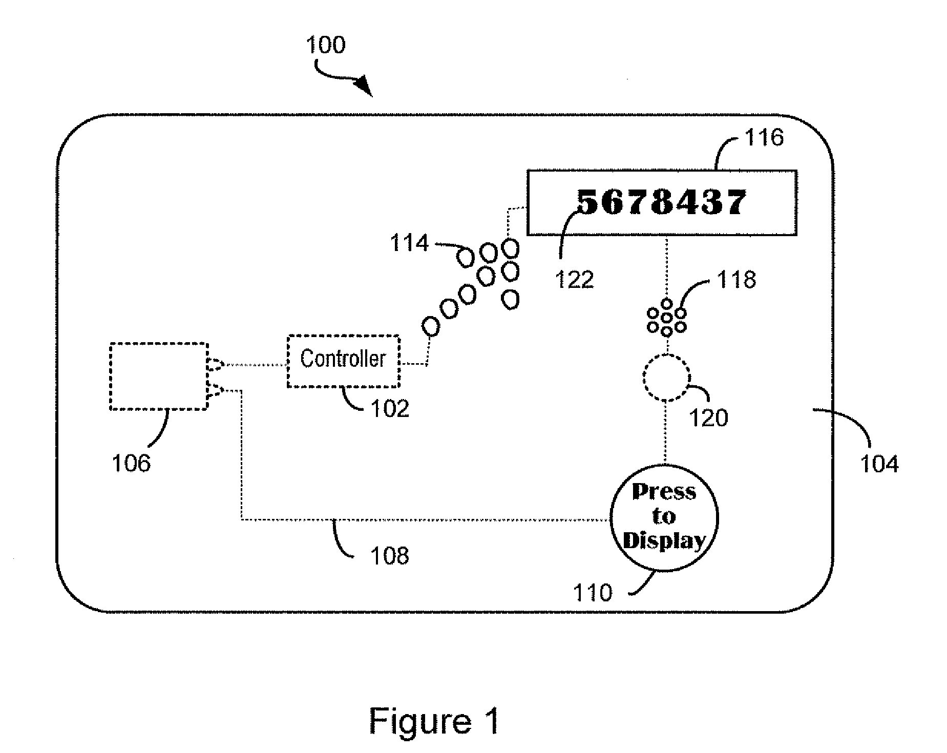
[0029]An exemplary powered card comprises a thin, flexible substrate (e.g., paper, thin cardboard stock, or plastic) having an embedded battery and electrical circuitry. The powered card is preferably equal in size to a conventional credit card, and may meet at least the flexibility requirements of ISO 7816. Powered by the battery, the circuitry can activate electronic output devices that, for example, display an encrypted light array, display alphanumeric characters or graphics, or play a voice message. From this output, a user can obtain information necessary to complete a transaction, for example, authenticating access to a financial account. The card can be branded or printed and may be traded, collected, or distributed as part of a promotion.

[0030]The electrical circuitry can be activated by any means suitable fo...


PUM

PropertyMeasurementUnit
temperatureaaaaaaaaaa
areaaaaaaaaaaa

Abstract

Apparatuses and methods for packaging electronically powered cards are provided for maintaining electronically powered cards in a deactivated state. In an embodiment, a housing having a face panel and two side panels attached to the face panel at opposite sides is configured to provide an offset distance between an activation device on the card and the housing so that the activation device is prevented from being activated by a force exerted on the housing. Annular or circular devices can also be provided for establishing an offset distance between activation devices on the card and planar substrates.

Description

[0001]This application claims the benefit of U.S. Provisional Application No. 60 / 877,634, filed Dec. 29, 2006, which is herein incorporated by reference in its entirety.BACKGROUND[0002]1. Field of the Invention[0003]The present invention relates generally to powered ISO 7816-compliant cards and, more particularly, to apparatus for mailing powered cards in compliance with applicable postal regulations.[0004]2. Background of the Invention[0005]As a convenience for their customers, businesses (e.g., financial institutions), retailers, and advertisers routinely deliver transactional cards and promotional cards to their customers through the mail. The convenience of receiving a card through the mail saves a customer the trouble of visiting a retail location to pick up a card. As a result, the United States Postal Service (“USPS”) annually handles the mailing of millions of transactional cards, such as credit cards, debit cards, electronic cash cards, gift cards, pre-paid calling cards, I...

Claims


Application Information

Patent Timeline
Patent Type & Authority Patents(United States)
IPC IPC(8): G06K19/00
CPCA45C11/182B65D81/05A45C2011/186
Inventor LANDAU, STEVENTAYLOR, TERESA
Owner BRIGHTVOLT INC
Why Eureka
Try Eureka