Flat illumination device for illumination and backlighting with integrated emergency power supply

a technology of backlighting and illumination, which is applied in the field of flat lightemitting lighting devices for illumination and backlighting, can solve the problems of high energy consumption proportional to the number of leds, inconvenient installation, and inconvenient maintenance, and achieves energy-saving, low cost, and reduced current consumption.

Active Publication Date: 2012-05-22
AIRBUS OPERATIONS GMBH
View PDF15 Cites 4 Cited by
  • Summary
  • Abstract
  • Description
  • Claims
  • Application Information

AI Technical Summary

Benefits of technology

[0013]Organic light-emitting diodes (OLEDs) may have considerable application potential in the field of illumination technology, when compared to conventional light sources, OLEDs radiate as flat lit areas, with their distinguishing features being a larger angle of view, reduced current consumption, and furthermore the ability to be produced as very thin films or foils which may also be flexible. These flat layers can light up homogeneously and as a diffuse light source are particularly suited to applications in background illumination and display technology.
[0034]In particular in the field of aviation, flat, weight-saving luminous panels that may not require any recesses in the interior lining can be used for warning- or display devices. If the OLED layer or OLED layers is / are sandwiched between oxygen-impermeable polymer layers, the lighting device can be curved. As a result of the flexibility created in this way there is the option of affixing the lighting device on a multitude of surfaces. This is of great benefit in particular in the frequently encountered curved surfaces of interior cabins of aircraft.

Problems solved by technology

These illumination techniques are associated with a disadvantage in particular in that considerable construction depth is required in order to achieve homogeneous illumination.
Furthermore, in the case of lighting devices that use LED arrays as described in DE 199 08 404 A1 the use of several lighting means may result in high energy consumption proportional to the number of LEDs.
A number of between, for example, 30 and 60 LEDs results in a power consumption of between 2 and 4 watts.
In this way it may not be possible to use the benefit of the lower energy requirement of the individual LEDs to advantage.
The display device comprises several light sources, for example miniature lights with a comparatively high power consumption per lamp of approximately 2 W. Furthermore, the display comprises a multitude of individual parts, which may result in cost-intensive manufacture and in expensive installation work if changing the glass bulb lights becomes necessary.

Method used


Image

  • Flat illumination device for illumination and backlighting with integrated emergency power supply
  • Flat illumination device for illumination and backlighting with integrated emergency power supply
  • Flat illumination device for illumination and backlighting with integrated emergency power supply

Examples


Embodiment Construction

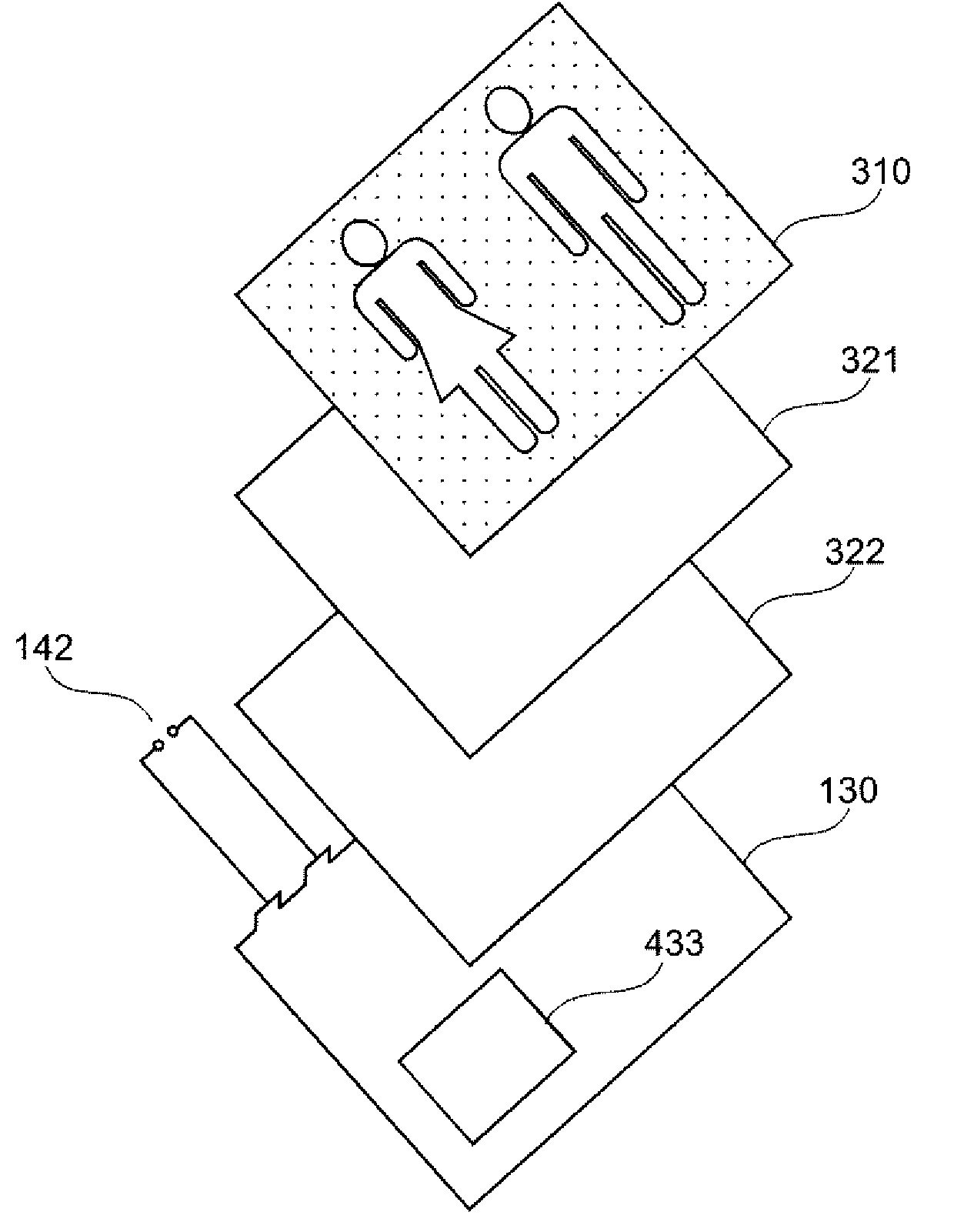
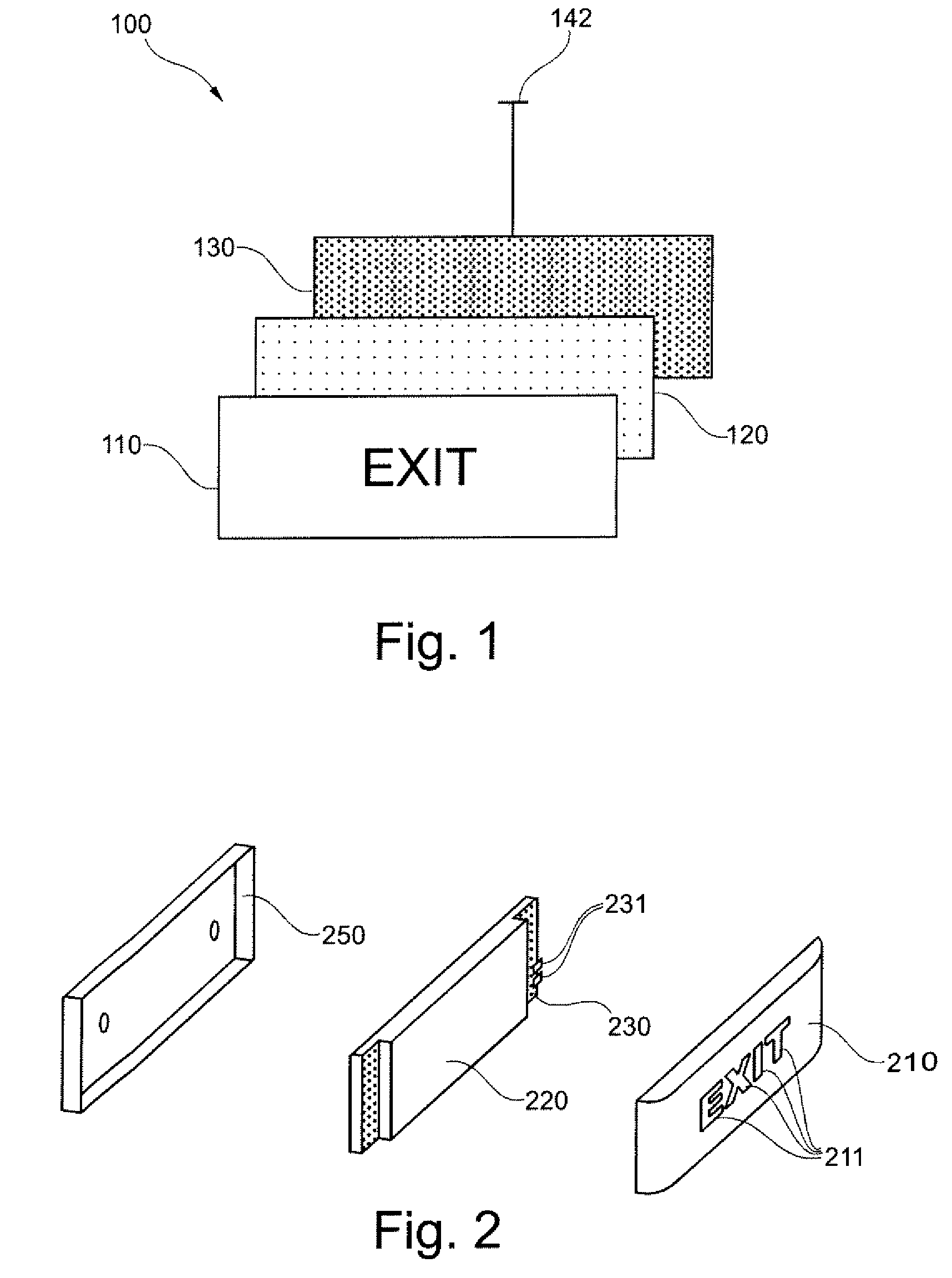
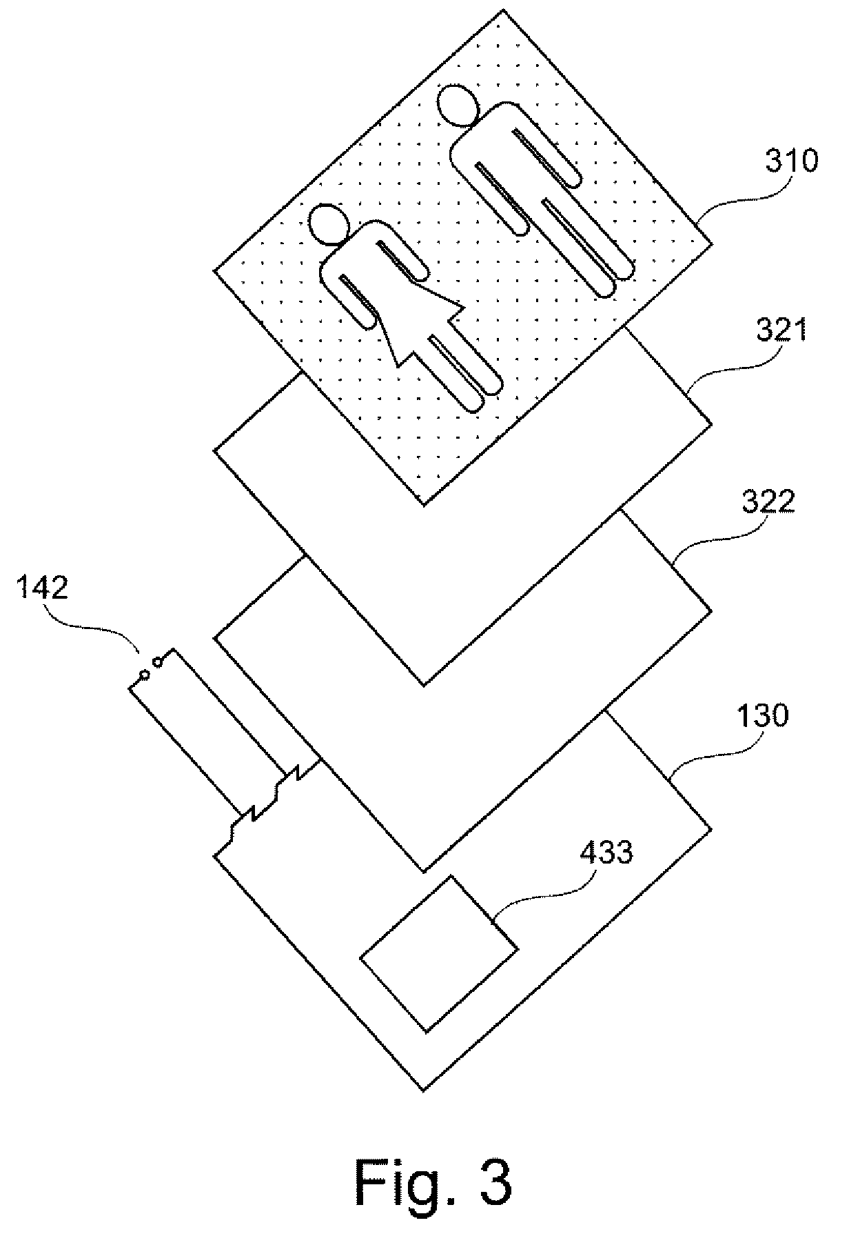
[0050]FIG. 1 shows a diagrammatic exploded view of a lighting device 100 according to an exemplary embodiment of the invention, comprising a carrier face 110, a flat illumination device 120 and an electronics unit 130 with an electrical supply line to the principal energy supply 142. The lighting device, which is shown as an example, is an illuminated information sign with the wording “EXIT” for marking the emergency exit, which signs are frequently used on board aircraft or ships. Emergency exits or escape routes can also be marked with the use of pictograms and additional information arrows. The carrier face 110 can, for example, be a film or foil that is bonded to the flat illumination device 120.

[0051]The flat illumination device 120 is, for example, a thin OLED lighting unit comprising one or several organic films or foils between each two electrodes. The electronics are diagrammatically indicated by the area 130; they are described in FIG. 4 with reference to an exemplary embo...


PUM


Abstract

The invention relates to a flat light-emitting lighting device for a vehicle, and to a method for providing emergency energy supply to the lighting device. A shallow installation depth and low power consumption of the lighting device may be ensured by the use of a flat OLED illumination device. Due to the low power consumption of the flat OLED illumination device, an emergency energy supply may be integrated without this increasing the installation depth. Such flat lighting devices, which in the case of emergency are self-supplying, may, for example, be used in aircraft in order to, with suitable icons or text, indicate escape routes or other emergency-relevant information.

Description

CROSS-REFERENCE TO RELATED APPLICATIONS[0001]This application claims the benefit of the filing date of U.S. Provisional Patent Application No. 61 / 137,971 filed Aug. 5, 2008, the disclosure of which is hereby incorporated herein by reference.BACKGROUND OF THE INVENTION[0002]The invention relates to lighting devices. In particular, the invention relates to a flat light-emitting lighting device for illumination and backlighting in vehicles, with integrated emergency power supply, to an aircraft, to the use, to a method, to a computer program element, and to a computer-readable storage medium.[0003]Illuminated displays for signage, for example icons or written text, are often required in the field of passenger transport, in particular in the context of aircraft or ships. Illumination that is usually used for warning signs or information, e.g. emergency exit signs, is implemented either with conventional light bulbs or LEDs. These illumination techniques are associated with a disadvantag...

Claims


Application Information

Patent Timeline
Patent Type & Authority Patents(United States)
IPC IPC(8): B64D47/02
CPCB60Q3/0256B60Q3/0259B60Q3/0283B60Q3/0293H02J9/065B60Q3/46B60Q3/47B60Q3/745B60Q3/80H02J2310/44Y02B70/30Y04S20/20
Inventor VOGEL, CARSTENHEYM, DETLEF
Owner AIRBUS OPERATIONS GMBH
Why Eureka
Try Eureka