

Wheel rotating device for in-wheel motor vehicle
a technology of rotating device and motor vehicle, which is applied in the direction of electric devices, electric propulsion mounting, gearing, etc., can solve the problems of affecting the miniaturization of the motor as a whole, affecting the output efficiency and the dynamics of the vehicle, and reducing the dynamic balance of the drive shaft system of the vehicle, so as to reduce the oscillation the effect of improving the static and dynamic balance of the drive shaft system and reducing the load
- Summary
- Abstract
- Description
- Claims
- Application Information
AI Technical Summary
Benefits of technology
Problems solved by technology
Method used
Image

Examples
Embodiment Construction
[0029]A detailed description will be given of exemplary embodiments of the present invention with reference made to the accompanying drawings where appropriate.
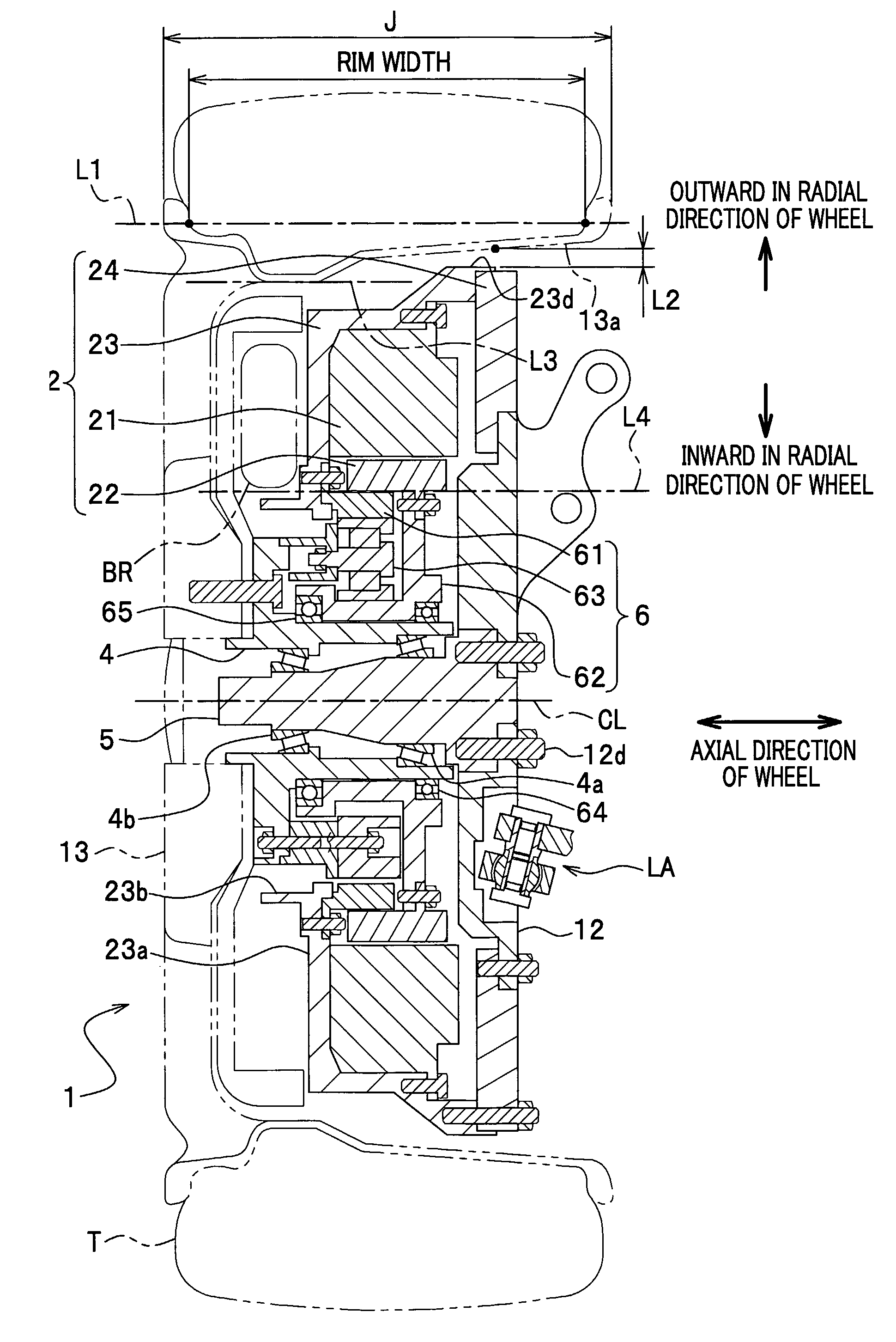
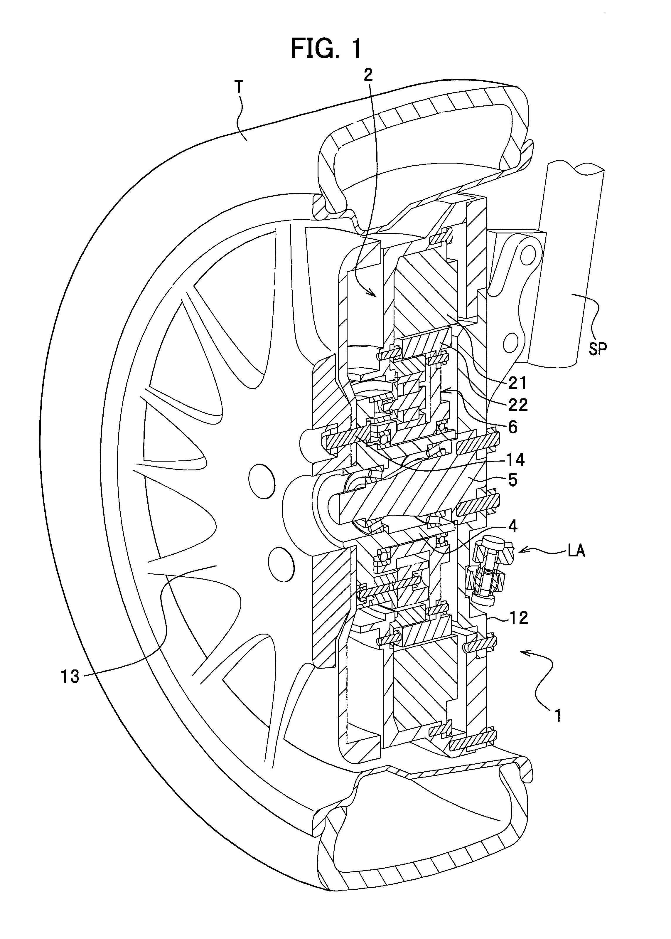
[0030]As shown in FIG. 1, a wheel rotating device 1 according to an exemplary embodiment of the present invention includes a motor 2 for generating a rotating force, a planetary gear train 6 that is coupled to an output part of the motor 2, a hub 4 that is coupled to an output part of the planetary gear train 6, and a spindle 5 that is fixed on a knuckle 12 and adapted to support a hub 4 in a manner that permits the hub 4 to rotate. These components of the wheel rotating device 1 are accommodated in a wheel 13.
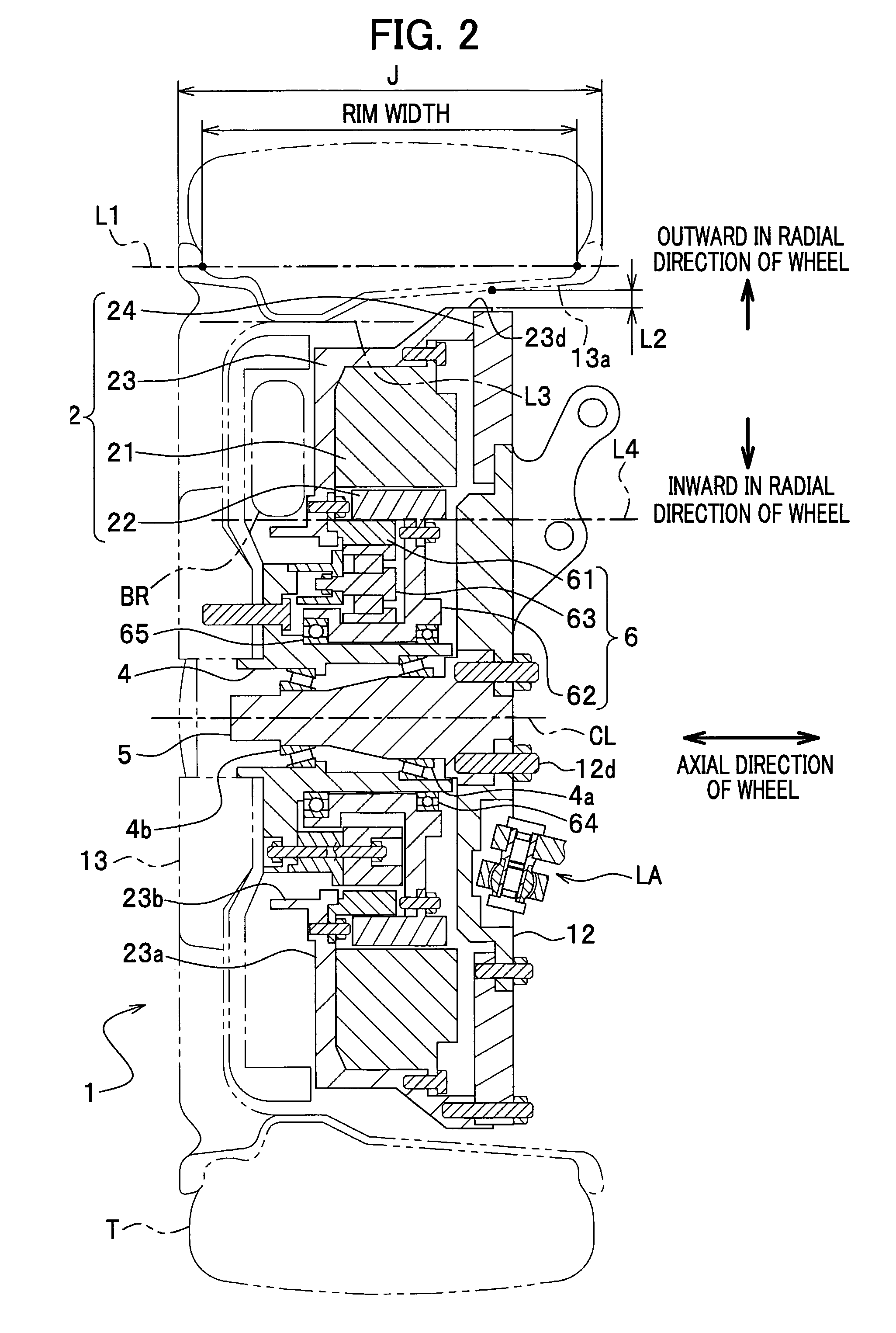
[0031]To be more specific, as shown in FIG. 2, the motor 2 is disposed along an inner circumferential surface 13a of the wheel 13, as opposed to the inner circumferential surface. Inside of the motor 2 is disposed the planetary gear train 6, and the planetary gear train 6 is coupled to the hub 4. The hub 4 is fitted ove...
PUM
 Abstract
Description
Claims
Application Information