Connecting head structure for high-pressure fuel injection pipes
a high-pressure fuel injection and connection head technology, which is applied in the direction of hose connection, combustion air/fuel-air treatment, machines/engines, etc., can solve the problems of cavitation erosion and other problems, and achieve the effect of increasing the width of both seat surfaces, reducing fatigue, and increasing the diameter and stress concentration
- Summary
- Abstract
- Description
- Claims
- Application Information
AI Technical Summary
Benefits of technology
Problems solved by technology
Method used
Image
Examples
first embodiment
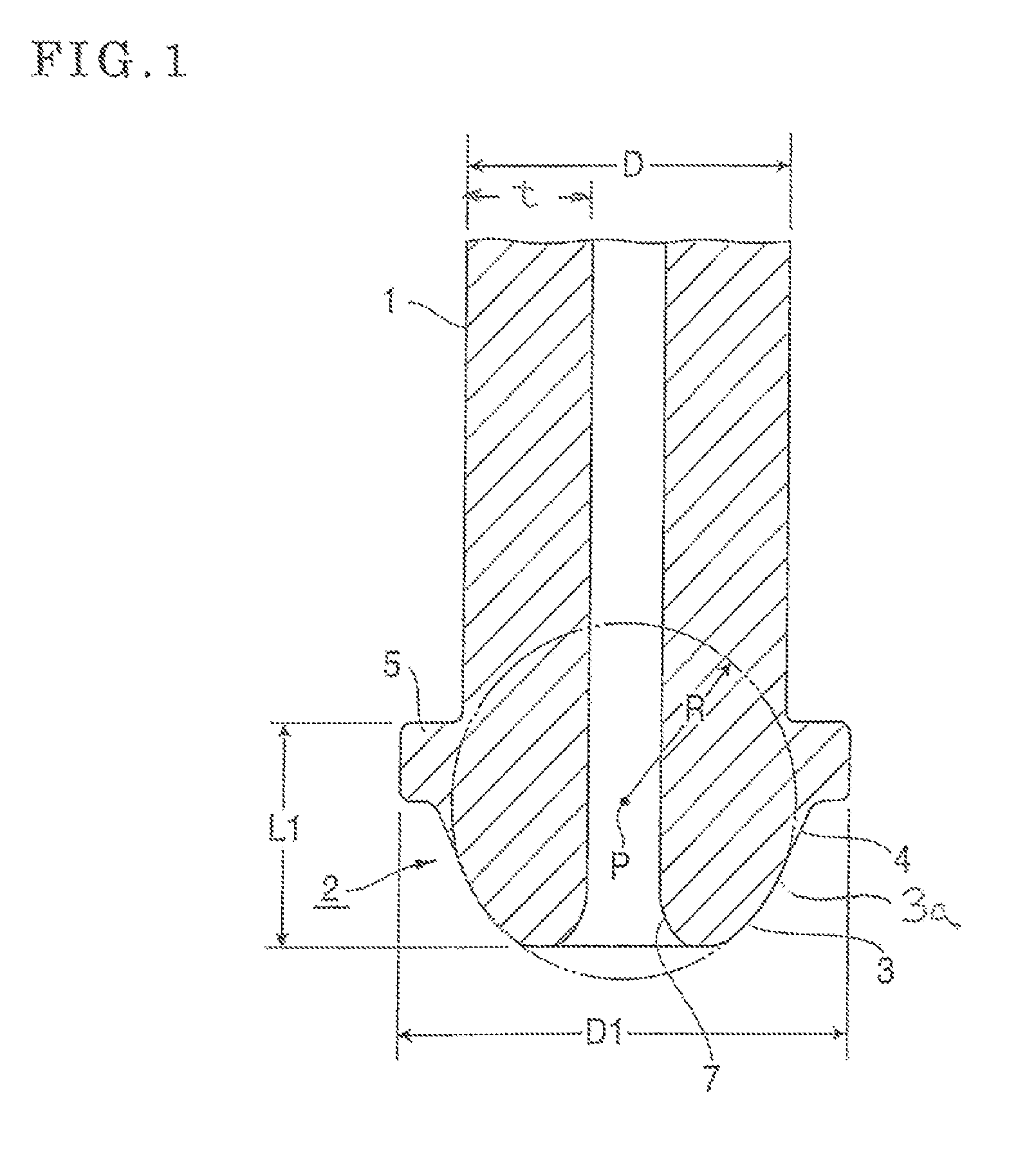
[0079]Using a thick-wall small-diameter steel pipe with the pipe diameter D of 8.0 mm, the pipe inner diameter Din of 4.0 mm and the thickness t of 2.0 mm (t / D=0.25), (material: EN E355), after the opening end of the steel pipe is chamfered, the connecting head shown in FIG. 1 is molded by the head molding method shown in FIG. 15. For the pipe diameter D and the thickness t of the thick-wall small-diameter steel pipe in this embodiment, the axial distance L1 from the connecting head end of the obtained connecting head to the annular flange portion back face, the spherical radius R of the seat surface, and the annular flange portion outer diameter D1 are L1=3.9 mm, R=4.2 mm, and D1=10.0 mm, respectively, but generation of a pocket (annular recess) is not found on the inner peripheral surface of the connecting head.
second embodiment
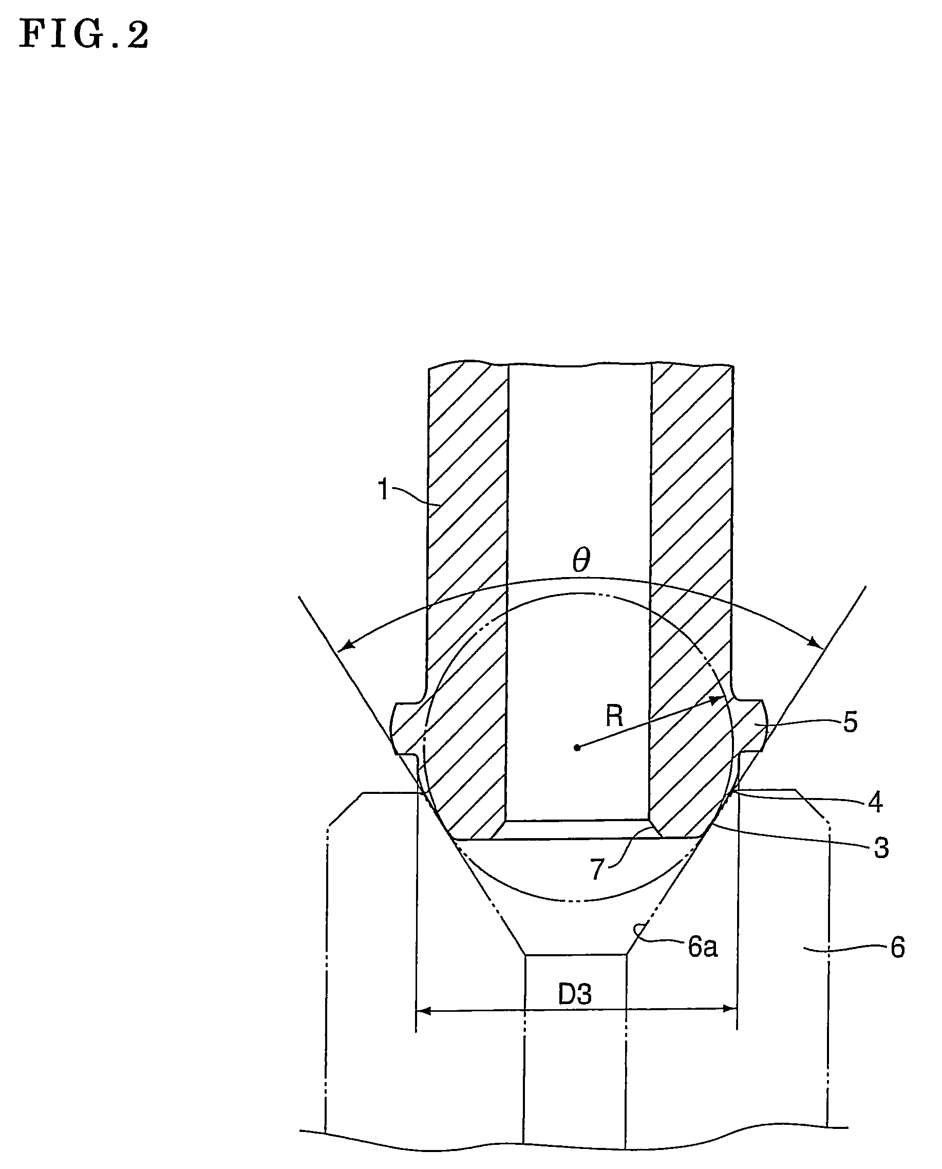
[0080]Using a thick-wall small-diameter steel pipe with the pipe diameter D of 8.0 mm, the pipe inner diameter Din of 4.0 mm and the thickness t of 2.0 mm (t / D=0.25) (material: EN E355), after the opening end of the steel pipe is chamfered, the connecting head with the sectional structure shown in FIG. 3 is molded using the punching member 11 with the root portion of the core metal 11-4 in the tapered configuration with a large diameter by the head molding method shown in FIG. 15. For the pipe diameter D and the thickness t of the thick-wall small-diameter steel pipe in this embodiment, the axial distance L1 from the connecting head end of the obtained connecting head to the annular flange portion back face, the spherical radius R of the seat surface, the annular flange portion outer diameter D1, the vertex angle θ of the conical surface and the maximum diameter D3 of the conical surface are L1=3.9 mm, R=4.2 mm, D1=10.0 mm, θ=56 degrees, and D3=8.5 mm, and the hardness of the vicini...
third embodiment
[0082]Using a thick-wall small-diameter steel pipe with the pipe diameter D of 6.0 mm, the pipe inner diameter Din of 3.0 mm and the thickness t of 1.5 mm (t / D=0.25) (material: EN E355), after the opening end of the steel pipe is chamfered, the connecting head with the conical surface shown in FIG. 12 is molded using the punching member 11 with the root portion of the core metal 11-4 in the tapered configuration with a large diameter by the head molding method shown in FIG. 15. For the pipe diameter D, the pipe inner diameter Din, and the thickness t of the thick-wall small-diameter steel pipe in this embodiment, the axial distance L1 from the connecting head end of the obtained connecting head to the annular flange portion back face, the spherical radius R of the seat surface, the annular flange portion outer diameter D1, the taper depth LT of the conical surface, and the tip-end opening diameter DT are L1=3.0 mm, R=3.75 mm, D1=8.4 mm, LT=2.8 mm, DT=4.2 mm, and generation of a pock...
PUM
| Property | Measurement | Unit |
|---|---|---|
| vertex angle | aaaaa | aaaaa |
| vertex angle θ1 | aaaaa | aaaaa |
| vertex angle θ2 | aaaaa | aaaaa |
Abstract
Description
Claims
Application Information
 - R&D
- Intellectual Property
- Life Sciences
- Materials
- Tech Scout
- Unparalleled Data Quality
- Higher Quality Content
- 60% Fewer Hallucinations
Browse by: Latest US Patents, China's latest patents, Technical Efficacy Thesaurus, Application Domain, Technology Topic, Popular Technical Reports.
© 2025 PatSnap. All rights reserved.Legal|Privacy policy|Modern Slavery Act Transparency Statement|Sitemap|About US| Contact US: help@patsnap.com


