

Attachment of absorbable tissue scaffolds to fixation devices
a bioabsorbable tissue and implant device technology, applied in the direction of surgical staples, prostheses, mechanical equipment, etc., can solve the problems of damage to the scaffold, limitations on the previously disclosed methods and devices, and the need for a multi-step fastening process
- Summary
- Abstract
- Description
- Claims
- Application Information
AI Technical Summary
Problems solved by technology
Method used
Image

Examples
example 1
Polymeric Melt Adhesion of the Tissue Engineering Scaffold Component to the Fixation Component
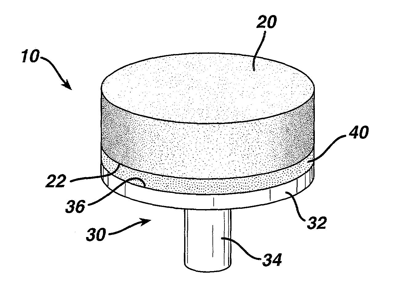
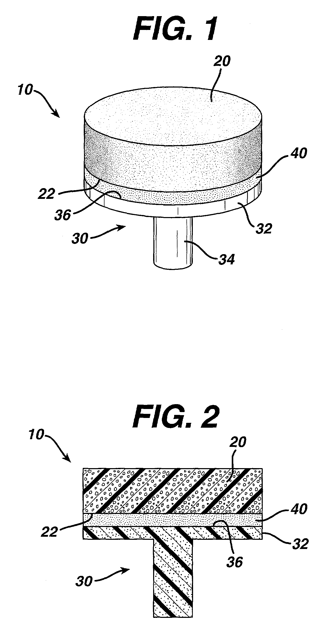
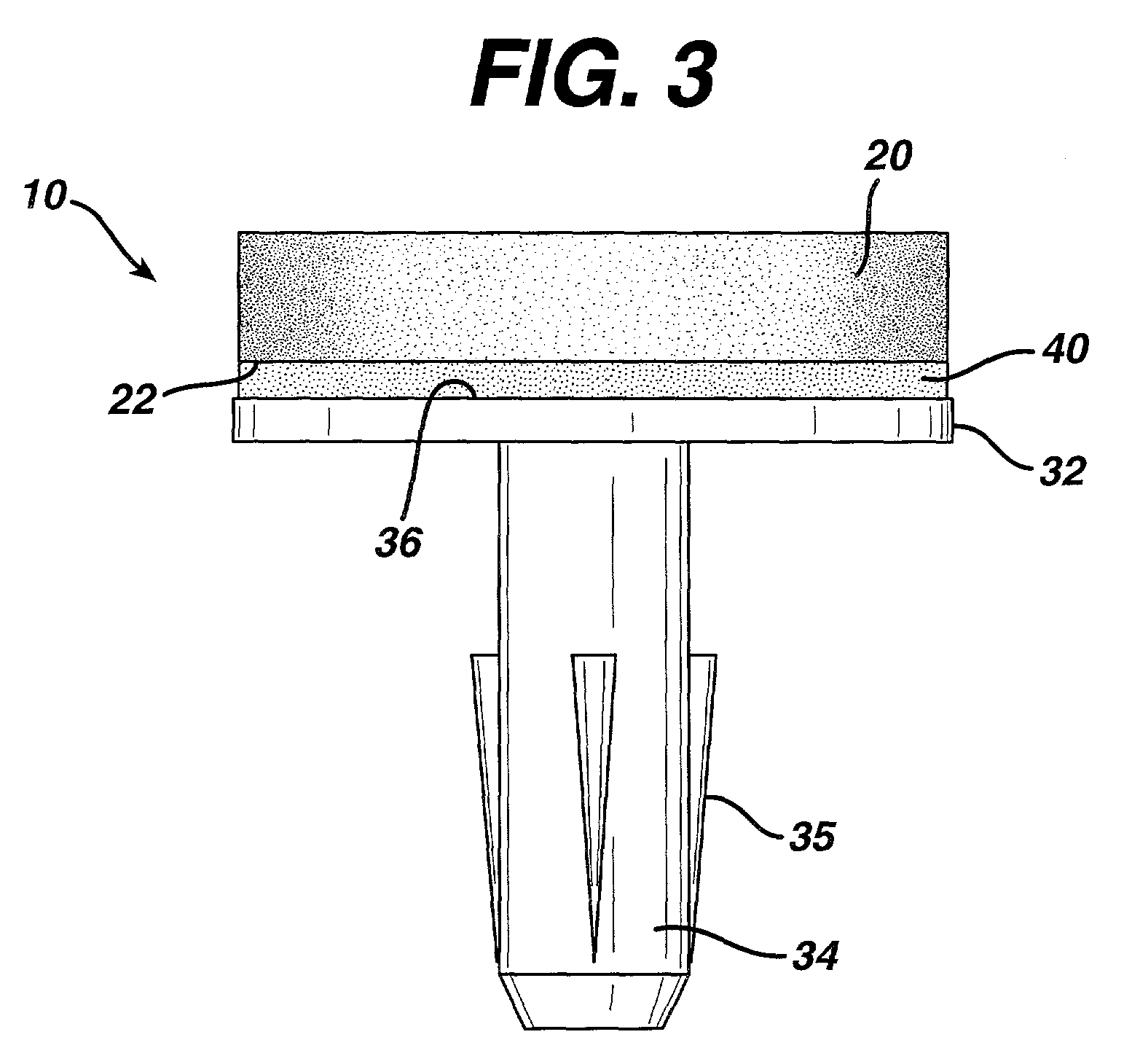
[0044]Bioabsorbable fixation components were manufactured using an injection molding process. The design of the fixation component used is the same as that depicted in FIG. 3. The polymer used to manufacture the fixation components was a copolymer of 85% PLA and 15% PGA (85 / 15 PLA / PGA) produced by Purac (Gorinchem, The Netherlands), with an I.V. of 1.79 dL / g as measured in chloroform. The injection molder (Niigata NN35MI) had a barrel diameter of 18 mm. The hopper was fitted with a nitrogen purge to keep the polymer dry. The feed, transition and compression zone temperatures were 185° C., 185° C. and 191° C., respectively. The die and mold temperatures were 191° C. and 240° C., respectively. The maximum injection speed was 80 mm / s and maximum injection pressure was 85 Kgf / cm2. The hold pressure was 70 Kgf / cm2. The total time for injection and hold was 3 seconds and the cooling time at the e...
example 2
PLA / PGA Copolymer / Solvent Solution Adhesion of the Tissue Engineering Scaffold to the Fixation Device
[0052]Seven millimeter diameter disks of scaffold component were prepared as discussed in Example 1. Fixation components with scaffold supports that were seven millimeters in diameter were also prepared as discussed in Example 1.
[0053]A bioabsorbable 85 / 15 copolymer of PLA / PGA (produced by Purac Biochem, the Netherlands) was dissolved in ethyl acetate. A five percent weight copolymer solution was obtained by heating the solution at approximately 60° C. during gentle agitation.
[0054]The scaffold component was placed on the scaffold support of the fixation component. A disk of PTFE (poly(tetrafluoroethylene)) was placed on the scaffold component. The scaffold component was then saturated with the copolymer solution. A weight of between 15 and 16 grams was applied to the PTFE disk to hold the scaffold component firmly against the scaffold support. The solution was then allowed to dry in...
example 3
PCL / PLA Copolymer / Solvent Solution Adhesion of the Tissue Engineering Scaffold to the Fixation Device
[0055]Seven millimeter diameter disks of scaffold component were prepared as discussed in Example 1. Fixation components with scaffold supports that were seven millimeters in diameter were also prepared as discussed in Example 1.
[0056]A bioabsorbable 40 / 60 copolymer of PCL / PLA (produced by Birmingham Polymers, Birmingham, Ala.) was dissolved in ethyl acetate. A five percent weight copolymer solution was obtained by heating the solution at approximately 60° C. during gentle agitation.
[0057]The scaffold component was placed on the scaffold support of the fixation component. A disk of PTFE (poly(tetrafluoroethylene)) was placed on the scaffold component. The scaffold component was then saturated with the copolymer solution. A weight of between 15 and 16 grams was applied to the PTFE disk to hold the scaffold component firmly against the scaffold support. The solution was then allowed to...
PUM
| Property | Measurement | Unit |
|---|---|---|
| Solubility (mass) | aaaaa | aaaaa |
| Adhesivity | aaaaa | aaaaa |
| Biocompatibility | aaaaa | aaaaa |
Abstract
Description
Claims
Application Information