Monolithic optical flow cells and method of manufacture

a technology of optical flow cells and monolithic crystals, applied in glass tempering devices, manufacturing tools, instruments, etc., can solve the problems of difficult to achieve the combination of square/square cross-sectional geometries, difficult to achieve wall flatness, and fundamental performance limits of instruments of the type noted, etc., to achieve the effect of improving the yield of useful flow cells, less subject, and improving differentiation

Active Publication Date: 2012-05-29
BECKMAN COULTER INC
View PDF14 Cites 71 Cited by
  • Summary
  • Abstract
  • Description
  • Claims
  • Application Information

AI Technical Summary

Benefits of technology

[0015]In view of the foregoing discussion, an object of this invention is to provide an improved method for making optical flow cells in which the interior flow channel is prismatic, a method that provides a significantly improved yield of useful flow cells manufactured that are less subject to failure over time, and a method that provides flow cells enabling better differentiation of various types of formed bodies.

Problems solved by technology

The fundamental performance limit of instruments of the type noted above originates in the transduction of formed-body properties into the characterizing parameters used to assign individual formed bodies to specific subpopulations.
However, in other cytometric applications where such optical parameters are combined with simultaneously determined non-optical parameters, in particular those based on the Coulter Principle (discussed below), the transverse cross-section and length of the flow-cell channel must be dramatically restricted to achieve suitable signal strength.
This combination of square / square cross-sectional geometries, wall thickness, wall surface parallelism, and wall flatness is difficult to achieve.
Although useful prismatic flow cells have been produced by the above-described planarization process, the yield of reliably functioning flow cells processed to contain a volumeter conduit has proven to be very low, typically less than 1 in 3.
More importantly, flow cells made by the planarization process (e.g., flow cell 30 in FIG. 13) are prone to subsequent failure modes: Firstly, irregularities and air pockets in the fused joins characteristic of the planarization approach result in localized heating due to the RF component of the conduit excitation current, with consequent failure of the join; secondly, some flow cells demonstrating longevity under RF exposure show join-dependent unit-to-unit variability in optical signals, even though joins are systematically positioned relative to the axis of optical excitation; thirdly, join imperfections tend to enlarge when sample flows are accompanied by significant cyclic pressure; and finally, flow cells left in stored apparatus tend to separate along the joins due to crystallization of salts if residual reagents are allowed to evaporate.
The '107 patent notes that optical and mechanical characteristics of said structure proved suboptimal, the adhesive joins potentially fluorescing or separating, but provides no alternative joining method.
As will be appreciated, multiple joins, subject to the same disadvantages as those occurring in the above-described planarization process, are required in flow cells including a plurality of such fused elements.
Further, the demands of machining the apexes from multiple elements, assembling the elements together, and joining them to attain repeatable polygonal conduits having the desired conduit dimensions make this approach both more costly and even less attractive as a production process.
This approach becomes increasingly disadvantageous as the number of prismatic faces increases.
However, the manufacture of such prismatic flow cells by any of the above-noted conventional techniques would be so complex and time-consuming as to be totally impractical, especially if such flow cells were to be made in relatively large numbers for incorporation into commercial cytometric instruments.
However, because both the optically transparent envelope and the central interior volumeter conduit of such flow cells exhibit a substantially circular transverse cross-section, the wall of such flow cells acts as a non-axisymmetric lens, and scatter (S) signals acquired through it incur substantial optical aberrations that limit the ability to differentiate between certain types of formed bodies.
While such differentiation can be improved by adding fluorescence (F) signals at different wavelengths, e.g., by selectively tagging the formed bodies with fluorescent dyes or dye-bead conjugates, such F signals are even more disadvantageously affected by optical aberrations than are the various scatter signals.
As noted, however, such flow cells are both difficult to produce using conventional production methods and subject to failure over time.
Thus, although others have proposed flow cells within which such simultaneous optical, or optical and Coulter, measurements may be made on individual formed bodies flowing through a prismatic channel, no one has either reduced to practice a truly monolithic (i.e., joinless single-piece) flow cell suited to such applications or provided a technically enabling disclosure for doing so.

Method used


Image

  • Monolithic optical flow cells and method of manufacture
  • Monolithic optical flow cells and method of manufacture
  • Monolithic optical flow cells and method of manufacture

Examples


Embodiment Construction

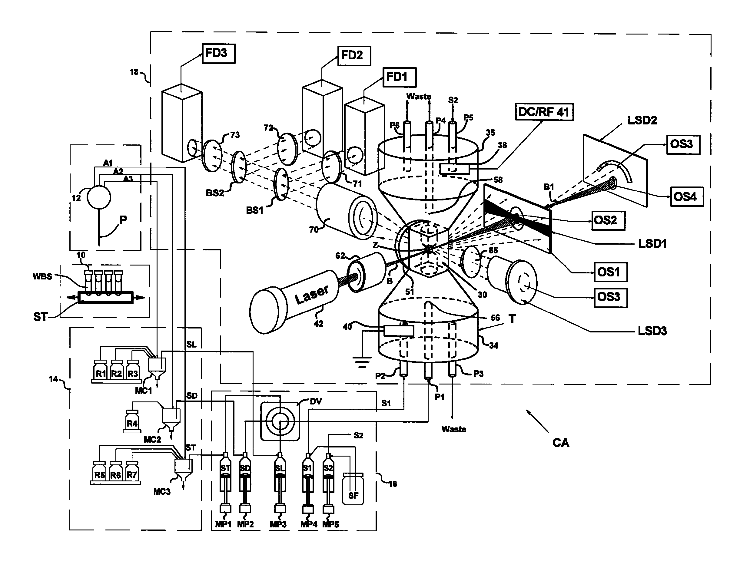
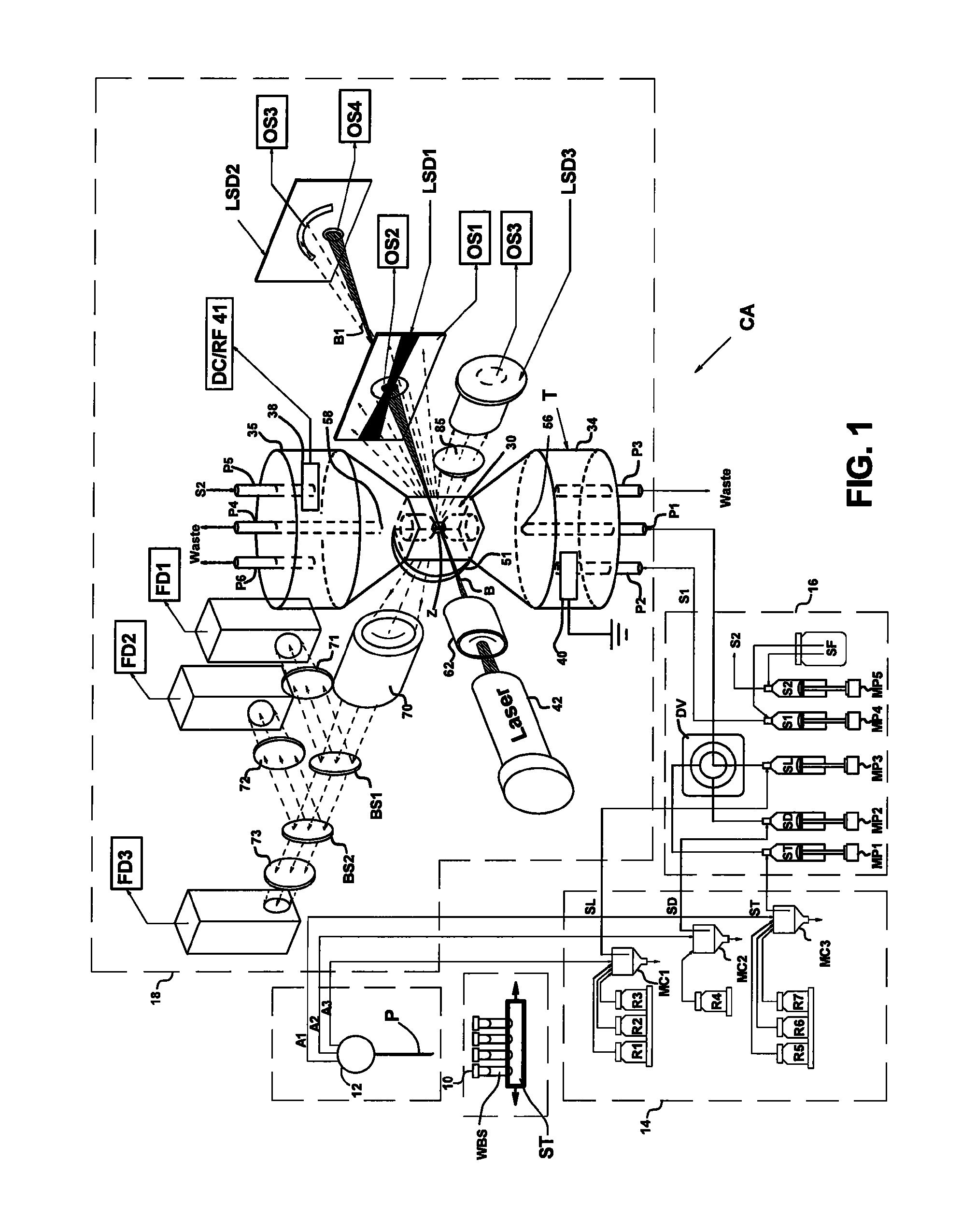
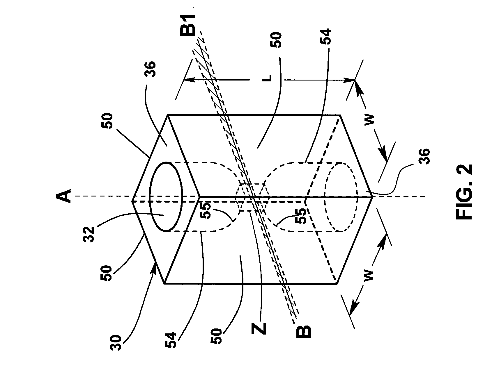
[0033]Flow cytometers acquire diagnostically important data from samples of patient body fluids containing various formed bodies, and many different embodiments have been developed. All depend on a channel in a flow cell through which such samples may be passed after undergoing various preparatory protocols and in which various properties of the formed bodies may be sensed, whereby the several types of subpopulations of formed bodies therein may be differentiated and enumerated and the derived parameters processed and correlated to provide desired diagnostics. As discussed above, flow cytometers incorporating simultaneous acquisition of optical and Coulter V and / or C parameters from an individual formed body require within the flow channel of their optical flow cells a constriction (or volumeter conduit) having relatively small lengths and transverse cross-sections. One such hematology analyzer is more fully disclosed in the above-noted U.S. Pat. No. 6,228,652, on which two of the p...


PUM

PropertyMeasurementUnit
lengthaaaaaaaaaa
lengthaaaaaaaaaa
thicknessaaaaaaaaaa

Abstract

An improved optical flow cell adapted for use in a flow cytometer for differentiating formed bodies (e.g., blood cells). Manufactured from a monolithic transparent material, the improved flow cell has an internal flow channel of polygonal transverse cross-section through which prepared samples can be metered and an external envelope suited to acquisition of optical parameters from formed bodies in such samples. Preferably, such flow cell is formed by a glass-drawing process in which a relatively large glass preform having a rectilinear internal channel of a desired polygonal cross-sectional shape is heated and drawn to achieve a desired cross-sectional area of reduced size. Also disclosed are preferred methods for differentiating formed bodies using the flow cell of the invention.

Description

CROSS-REFERENCE TO RELATED APPLICATIONS[0001]This application is a non-provisional application claiming the benefit under 35 U.S.C. §119(e) of U.S. Provisional Application No. 61 / 114,544, filed on Nov. 14, 2008, which is incorporated herein by reference in its entirety.BACKGROUND OF THE INVENTION[0002]1. Field of the Invention[0003]This invention relates generally to apparatus and methods for differentiating constituent types of formed bodies (e.g., cells or other small particles) in liquid samples (e.g., whole blood or other particle-suspending liquids). More particularly, this invention relates to improvements in optical flow cells of the type commonly used in flow cytometers (e.g., hematology and fluorescence flow cytometer instruments) that function to sense, differentiate, and characterize formed bodies by various optical transduction means, preferably in combination with non-optical parameters acquired via the Coulter Principle. The invention further relates to improvements in...

Claims


Application Information

Patent Timeline
Patent Type & Authority Patents(United States)
IPC IPC(8): G01N1/10
CPCC03B23/04C03B23/047C03B23/0476C03B23/057G01N15/1436G01N15/1459G01N2015/1037G01N2015/1486Y02P40/57
Inventor GRAHAM, MARSHALL DONNIEGRAHAM, WILLIAM GERRYCLARKIN, JAMES P.WELLS, MARK A.CANO, JOSE M.ARBOLEDA, CARLOS ALBERTOSANCHEZ, ARMANDO JOSE
Owner BECKMAN COULTER INC
Why Eureka
Try Eureka