Conical fluid dynamic bearings having improved stiffness for use in hard-disk drives

a technology of dynamic bearings and conical bearings, which is applied in the direction of sliding contact bearings, maintaining head carrier alignment, instruments, etc., can solve the problems of inability to accommodate such differences in bearing stiffness, inability to use symmetrical conical bearings, and inability to achieve the effect of high bearing stiffness

Active Publication Date: 2012-05-29
WESTERN DIGITAL TECH INC
View PDF15 Cites 4 Cited by
  • Summary
  • Abstract
  • Description
  • Claims
  • Application Information

AI Technical Summary

Benefits of technology

[0006]It is observed that, in practice, the upper cone and the lower cone of a fluid dynamic bearing (FDB) in a hard-disk drive (HDD) may bear different amounts of weight. For example, lower symmetrical cone 12 of FIG. 1 bears more weight than upper symmetrical cone 10 as lower symmetrical cone 12 bears more of the weight of the magnetic-recording disk(s) and motor structure. As a fluid dynamic bearing bears more weight, the fluid within the bearing compresses, thereby causing the bearing to become stiffer. As a result, when a HDD is oriented as shown in FIG. 1, lower symmetrical cone 12 will have a higher bearing stiffness than upper symmetrical cone 10, even though upper symmetrical cone 10 and lower symmetrical cone 12 have the same or substantially similar dimensions. The bearing stiffness between upper symmetrical cone 10 and lower symmetrical cone 12 may differ around 10% due to the disparity in how much weight is born by each bearing. FDB systems with symmetric cone designs can generally accommodate this disparity in stiffness between the upper and lower cones.

Problems solved by technology

As a fluid dynamic bearing bears more weight, the fluid within the bearing compresses, thereby causing the bearing to become stiffer.
However, certain spindle motors may require FDB designs that support a larger disparity in bearing stiffness (for example, a 200% difference) between the upper and lower conical bearings.
This need may arise due to an uncertainty in how much external force each conical bearing will eventually bear (which may be compounded because it may be unknown how the HDD will be oriented in the field).
A FDB system with a symmetric or substantially symmetrical conical bearing design may not be able to accommodate such difference in the bearing stiffness between the upper and lower conical bearings.
Also, as the form factor of HDDs becomes smaller and more compact, the space limitations within the HDD may render the use of symmetrical conical bearings impractical or impossible.

Method used


Image

  • Conical fluid dynamic bearings having improved stiffness for use in hard-disk drives
  • Conical fluid dynamic bearings having improved stiffness for use in hard-disk drives
  • Conical fluid dynamic bearings having improved stiffness for use in hard-disk drives

Examples


Embodiment Construction

[0019]Approaches for a fluid dynamic bearing (FDB) system that supports a greater disparity in the bearing stiffness between the conical bearings of the FDB system are described. In the following description, for the purposes of explanation, numerous specific details are set forth in order to provide a thorough understanding of the embodiments of the invention described herein. It will be apparent, however, that the embodiments of the invention described herein may be practiced without these specific details. In other instances, well-known structures and devices are shown in block diagram form in order to avoid unnecessarily obscuring the embodiments of the invention described herein.

Physical Description of Illustrative Embodiments of the Invention

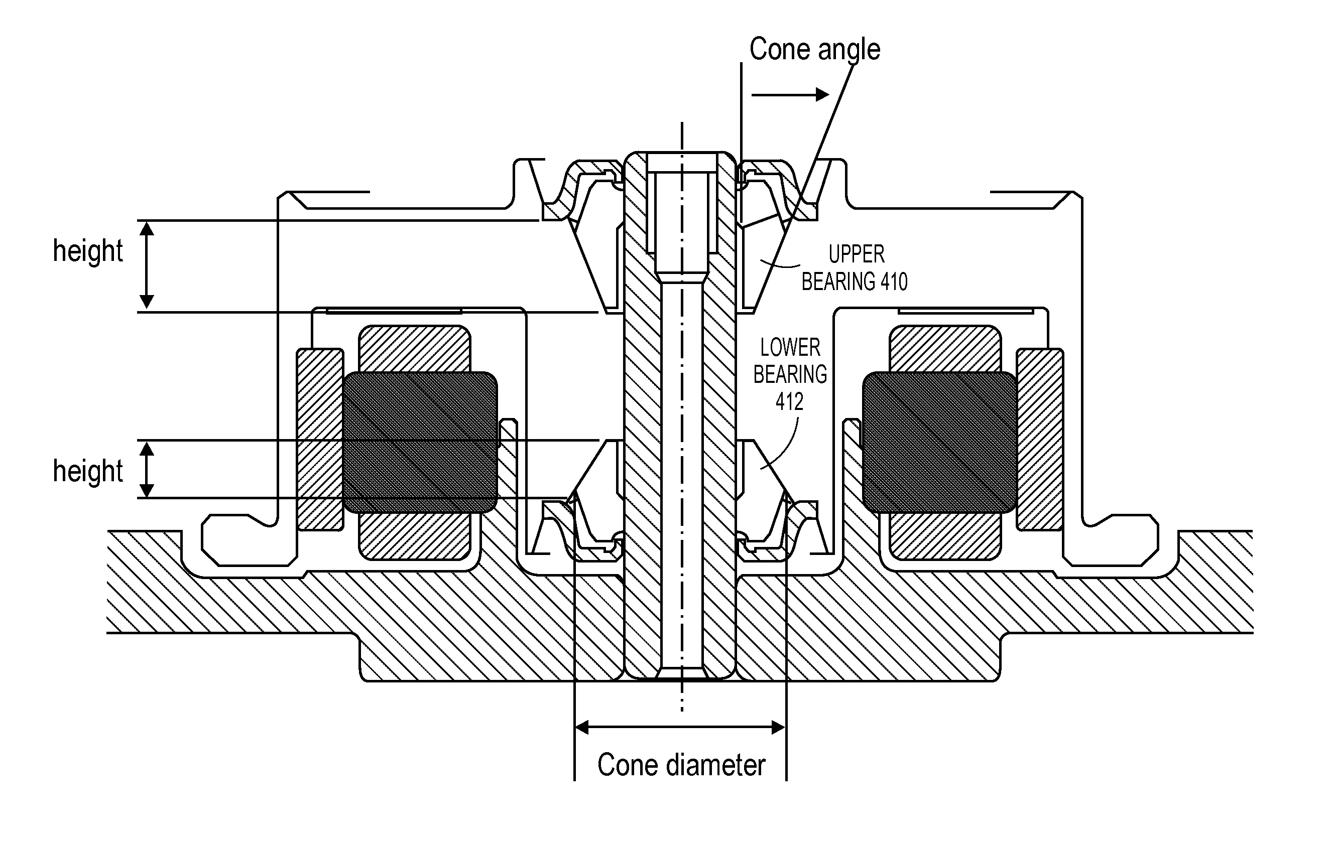
[0020]A fluid dynamic bearing (FDB) system according to embodiments of the invention supports a greater disparity in the bearing stiffness between the conical bearings of the FDB system. FIG. 5 is a diagram that shows the bearing stiffness...


PUM

PropertyMeasurementUnit
bearing stiffness ratioaaaaaaaaaa
anglesaaaaaaaaaa
cone angleaaaaaaaaaa

Abstract

Approaches for a fluid dynamic bearing (FDB) system for use within a hard-disk drive. A fluid dynamic bearing (FDB) system may comprise an upper conical bearing and a lower conical bearing that are both disposed along a stationary shaft on which a magnetic-recording disk is rotatably mounted. The upper conical bearing and the lower conical bearing may have different cone angles, diameters, and / or lubricants to produce a desired difference in stiffness between the first conical bearing and the second conical bearing. By adjusting characteristics of the fluid dynamic bearing (FDB) system to achieve the desired bearing stiffness ratio, the tendency for the magnetic-recording disks to experience a sustained vibration when the hard-disk drive receives a mechanical shock is reduced. By preventing the magnetic-recording disks from sustained vibration after a mechanical shock, data may be written to and read from the magnetic-recording disks with greater reliability.

Description

FIELD OF THE INVENTION[0001]Embodiments of the invention relate to conical fluid dynamic bearings (FDB) in a hard-disk drive (HDD).BACKGROUND OF THE INVENTION[0002]A hard-disk drive (HDD) is a non-volatile storage device that is housed in a protective enclosure and stores digitally encoded data on one or more circular disks having magnetic surfaces (a disk may also be referred to as a platter). When an HDD is in operation, each magnetic-recording disk is rapidly rotated by a spindle system. Data is read from and written to a magnetic-recording disk using a read / write head which is positioned over a specific location of a disk by an actuator.[0003]A read / write head uses a magnetic field to read data from and write data to the surface of a magnetic-recording disk. As a magnetic dipole field decreases rapidly with distance from a magnetic pole, the distance between a read / write head and the surface of a magnetic-recording disk must be tightly controlled. An actuator relies on suspensio...

Claims


Application Information

Patent Timeline
Patent Type & Authority Patents(United States)
IPC IPC(8): G11B17/02
CPCG11B19/2036F16C17/107F16C2370/12
Inventor KU, CHIAOPINGHUANG, FU-YINGHUANG, LIDUSHINDO, HITOSHI
Owner WESTERN DIGITAL TECH INC
Why Eureka
Try Eureka