
Method and device for monitoring a bearing clearance of roller bearings

a technology of roller bearings and clearances, which is applied in the direction of machines/engines, instruments, force/torque/work measurement apparatus, etc., can solve the problems of increasing distance, affecting the accuracy of measurement, so as to eliminate the influence of axial run-out and concentricity. , the effect of eliminating the influence of distance values

Active Publication Date: 2021-04-13
SCHAEFFLER MONITORING SERVICES GMBH
View PDF36 Cites 1 Cited by
  • Summary
  • Abstract
  • Description
  • Claims
  • Application Information

AI Technical Summary

Benefits of technology

The patent text describes a method for measuring bearing clearance by measuring the distance between the bearing surfaces in different load states. This is done by measuring the change in distance in at least two load states. The advantage of this method is that it can be done more easily and accurately compared to other methods. The text also discusses the influence of load states on the bearing clearance and how this can be used to reduce interfering influences. Additionally, it describes a method to eliminate distortion caused by axial run-out defects and concentricity defects by forming a floating mean value. Overall, the patent describes a more accurate and efficient method for measuring bearing clearance.

Problems solved by technology

If the bearing clearance increases (when it is positive) or the bearing preload is reduced due to said mechanisms, this leads, in the medium or long term, to consequential damage to the bearing system, as far as failure thereof.
It is however not possible to use this method to monitor wear, setting or releasing.
This is due to the fact that wear on the bearing having the adjustment device leads for example to an increase in distance, and wear on the opposing bearing leads to a reduction in distance.
The measurement is additionally overlaid with considerable temperature effects resulting from normal operation.
Such a device is therefore not suitable for monitoring the condition of a bearing clearance, but rather only for compensating thermal expansions.
It is also the case here that wear of the raceways and / or rolling bodies is not able to be detected unambiguously, since the measurement is distorted, on the one hand, by the temperature effects.
Both of the abovementioned approaches thus target the adjustment or constant maintenance of the operating clearance by compensating temperature influences, but are not however able to detect long-term changes to the preload or the bearing clearance caused by wear, setting or releasing.
However, these measurement methods require a multiplicity of sensors and complex preliminary calculations in order to determine the correlations.
One common feature of the cited prior art is that load changes during operation may greatly distort the control and / or measurement result, since such load changes likewise lead to distance changes.
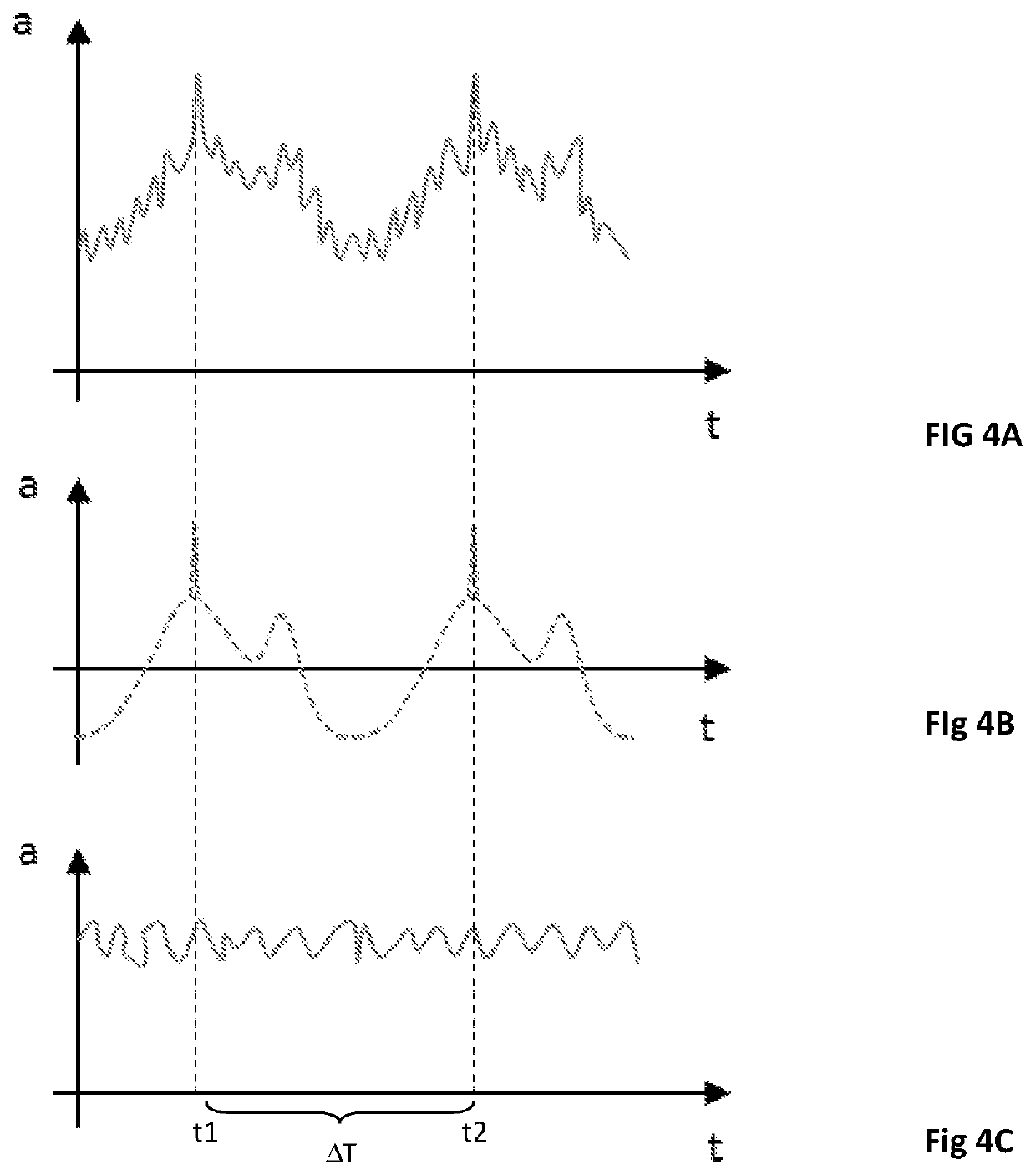
These may be axial run-out and concentricity defects, flatness and roundness deviations or surface defects.
If this is not taken into account in the evaluation, this may lead to extremely large scatter in the measurement result and call it into question.

Method used


Image

  • Method and device for monitoring a bearing clearance of roller bearings
  • Method and device for monitoring a bearing clearance of roller bearings
  • Method and device for monitoring a bearing clearance of roller bearings

Examples


Embodiment Construction

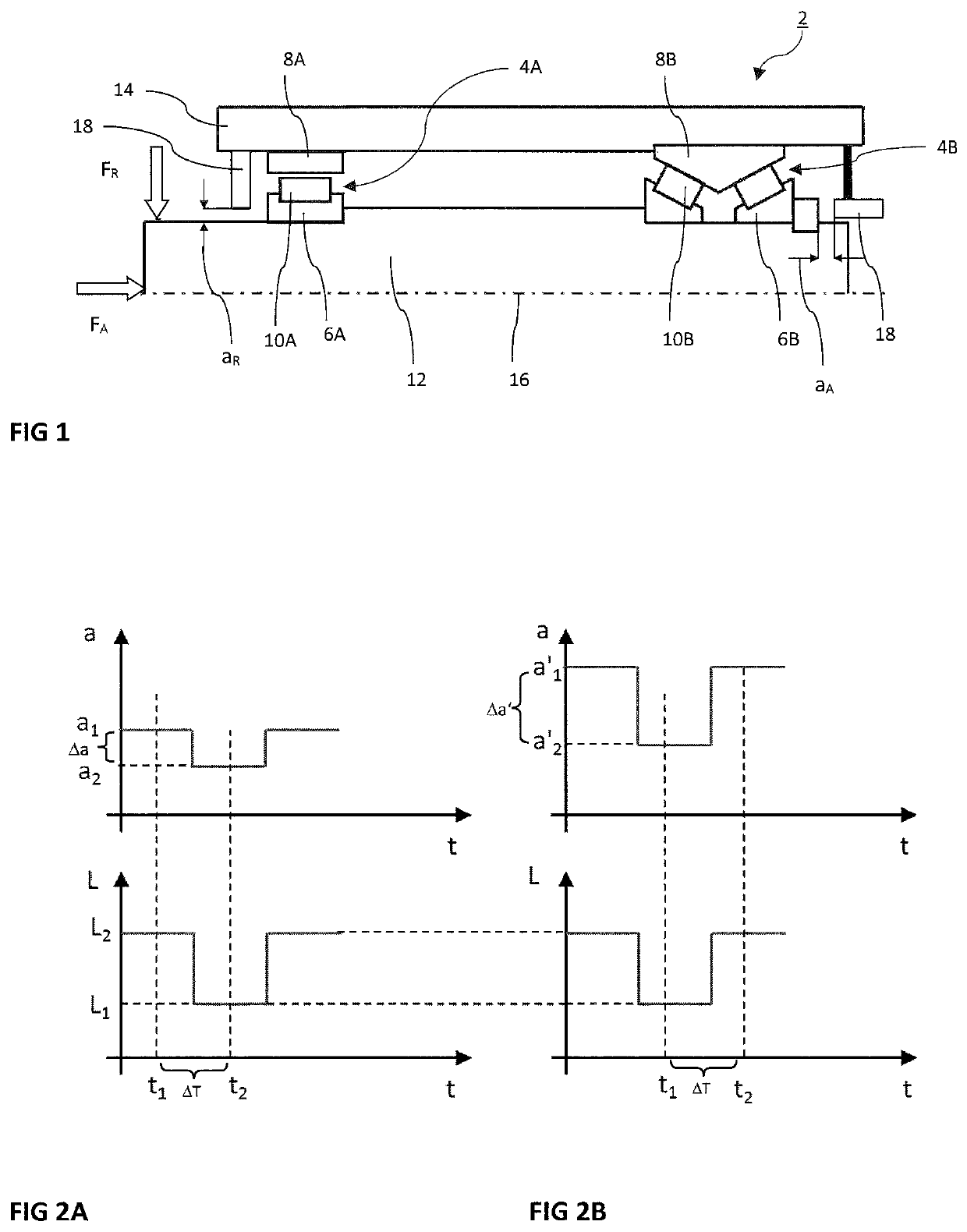
>[0070]FIG. 1 illustrates a bearing unit 2 by way of example and in highly schematic form. The illustrated bearing unit 2 is not necessarily a real situation, but rather FIG. 1 serves to explain different states. In the illustrated FIG. 1, the bearing unit 2 has two roller bearings 4 that are spaced from one another. The roller bearing 4B illustrated in the right-hand half of the image is in this case designed as a double-row, mounted and preloaded roller bearing. The roller bearing 4A illustrated in the left-hand half of the image is by contrast designed as a single-row roller bearing in the form of a floating bearing with positive bearing clearance (in contrast to the negative bearing clearance in the case of a preloaded bearing).

[0071]A respective roller bearing 4A or 4B in each case has at least an inner ring 6A or 6B, an outer ring 8A or 8B and rolling bodies 10A or 10B arranged between them. In the case of the roller bearing 4A illustrated in the left-hand half of the image wi...


PUM


Abstract

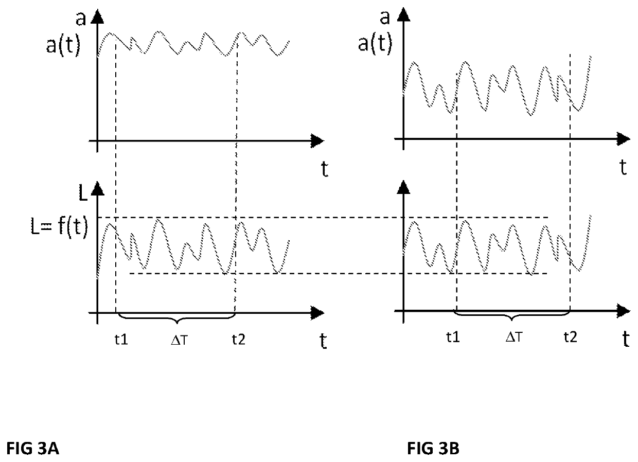
In the methods for monitoring a bearing clearance of a roller bearing (4), in particular the bearing clearance of a main bearing of a wind turbine, within the scope of a first measuring series using at least one distance sensor (18), a distance (a, a1, a2) between a rotating part (12) and a stationary part (14) is respectively sensed in at least two different recurring load states (L1, L2), and a difference (Δa) between the measured distances (a1, a2) is determined. At a later time the distance measurements are repeated in the same at least two recurring load states (L1, L2) within the scope of a second measuring series. A change in the bearing clearance is inferred on the basis of the changes in the distance difference (Δa) within the scope of condition monitoring.

Description

BACKGROUND OF THE INVENTIONField of the Invention[0001]The invention relates to a device and to a method for monitoring the state of the bearing clearance of a roller bearing, in particular the bearing clearance of a large bearing, specifically of a wind turbine, and in particular of a main bearing.Description of the Background Art[0002]State monitoring is in this case performed after the roller bearing is installed. Bearing clearance is understood to mean both a positive bearing clearance with bearing play and a negative bearing clearance (preloaded bearing) of roller bearing units. A roller bearing unit means in particular an individual bearing with attached parts (for example torque bearing) or a shaft system consisting of a shaft and a housing and any number of roller bearings.[0003]The bearings to be monitored are in general rotary bearings, that is to say bearings that rotate continuously about an axis of rotation during operation (and do not pivot just within a limited angula...

Claims


Application Information

Patent Timeline
IPC IPC(8): F16C19/38F16C19/52G01M13/04F16C41/00G01L5/00
CPCF16C19/38F16C19/522G01L5/00G01M13/04F16C41/00F16C2233/00F16C19/386F16C2229/00F16C2300/14F16C2360/31F03D80/70F03D17/00F05B2240/50Y02E10/72
Inventor REICHHART, MARC
Owner SCHAEFFLER MONITORING SERVICES GMBH
Learn More