Connector device for connecting rod part

A joint device and connecting rod technology, which is applied in the direction of construction and building construction, can solve the problems of difficult processing, poor versatility, troubles, etc., and achieve the effects of avoiding laborious transportation, easy processing, and simple processing

Active Publication Date: 2014-09-24
王华才
View PDF6 Cites 2 Cited by
  • Summary
  • Abstract
  • Description
  • Claims
  • Application Information

AI Technical Summary

Problems solved by technology

[0002] In the current field of construction and machinery, structural rods made of high-strength materials such as organic polymer materials, alloy materials or composite materials are widely used, for example, beams and columns of houses, towers, tower body standard sections of tower cranes Sections and mine channel structural frames, etc.; the traditional connection methods of structural rods mainly include: through multiple angle irons and welding, custom matching connectors according to connection requirements, and shell-shaped sleeves to complete rods with low load requirements Parts connection; the existing various space structures, or need to be welded in advance before use and then carry out troublesome transportation, or connect with simple structure through angle iron, shell-shaped sleeve head, or need to use a wide variety, difficult processing, versatility Poor joint device for customized installation, but lacks a highly standardized joint device that can quickly connect rods to form a variety of spatial structures and does not need to be welded in advance

Method used


Image

  • Connector device for connecting rod part
  • Connector device for connecting rod part
  • Connector device for connecting rod part

Examples


Embodiment Construction

[0037] The present invention provides many applicable inventive concepts that can be embodied in numerous specific contexts. The specific examples described in the following embodiments of the present invention are only used as illustrations of specific implementations of the present invention, and are not intended to limit the scope of the present invention.

[0038] The specific implementation of the present invention will be further illustrated below in conjunction with the accompanying drawings and specific embodiments.

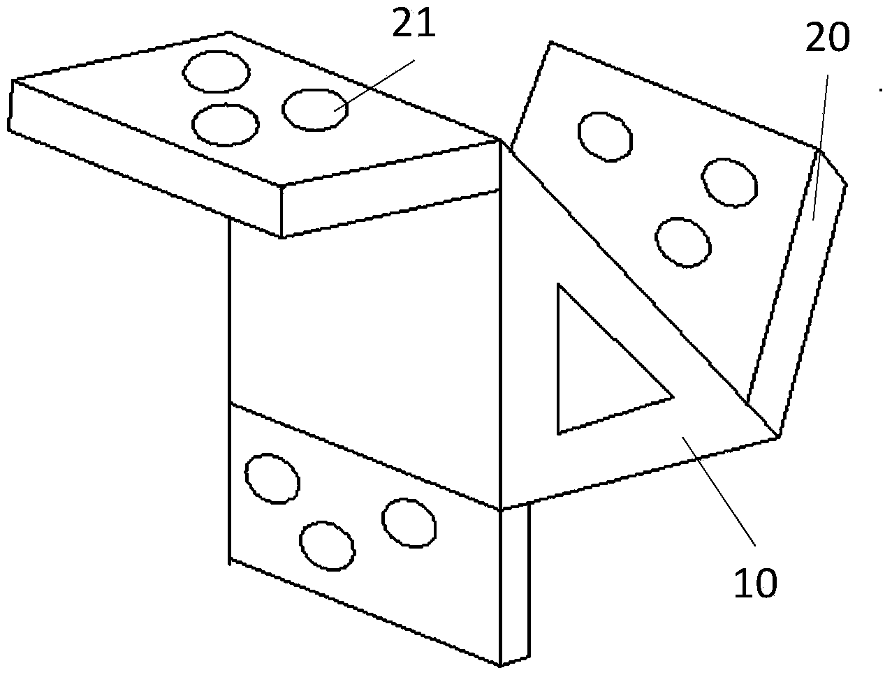
[0039] The present invention proposes a joint device for connecting rods, comprising:

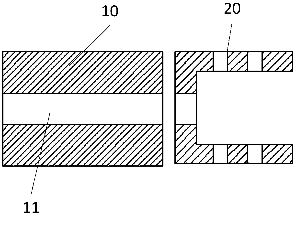
[0040] A solid or hollow body 10, wherein the shape of the body 10 includes: a triangular prism, a cube or a regular tetrahedron;

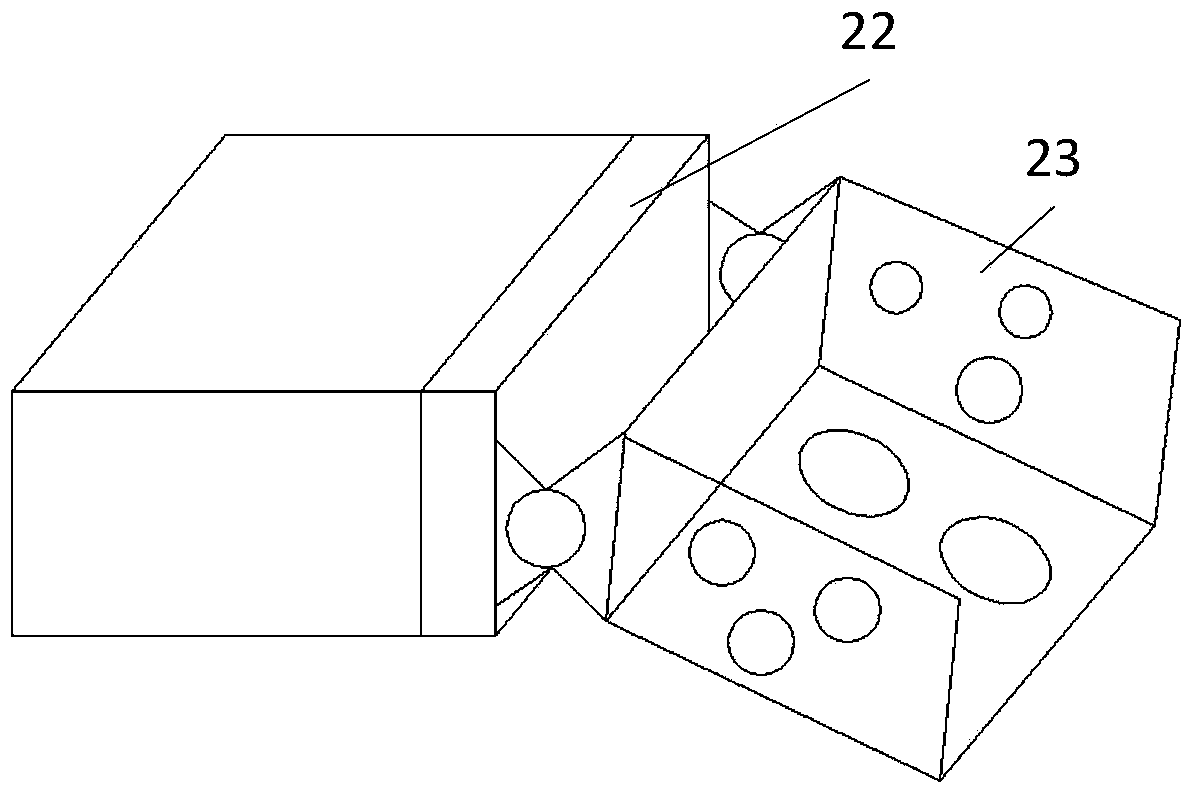
[0041] At least one connecting end 20, the connecting end 20 is arranged on the surface of the main body 10; wherein,

[0042] The structure of the connecting end 20 includes: a strip frame structure, wherein the cross section of the str...


PUM


Abstract

The invention discloses a connector device for connecting rod parts. The connector device comprises a solid or hollow main body and at least one connecting end which is arranged on the surface of the main body, wherein the main body is in a triangular prism shape or a cube shape or a regular tetrahedron shape. Each connecting end structurally comprises a long-stripe frame structure, wherein the cross section of the long-stripe frame structure is at least in an 'L' shape or a 'groove' shape or a '-' shape or a '=' shape or a 'T' shape or a '+' shape or an 'H' shape. First through holes are formed in the connecting ends, the main body is connected with the rod parts through the first through holes, and the connecting ends are distributed on the surface of the main body according to the spatial positions of the rod parts.

Description

technical field [0001] The invention relates to the fields of machinery and construction, in particular to a joint device for connecting rods. Background technique [0002] In the current field of construction and machinery, structural rods made of high-strength materials such as organic polymer materials, alloy materials or composite materials are widely used, for example, beams and columns of houses, towers, tower body standard sections of tower cranes Sections and mine channel structural frames, etc.; the traditional connection methods of structural rods mainly include: through multiple angle irons and welding, custom matching connectors according to connection requirements, and shell-shaped sleeves to complete rods with low load requirements Parts connection; the existing various space structures, or need to be welded in advance before use and then carry out troublesome transportation, or connect with simple structure through angle iron, shell-shaped sleeve head, or need...

Claims


Application Information

Patent Timeline
Patent Type & Authority Applications(China)
IPC IPC(8): E04B1/58
Inventor 王华才
Owner 王华才
Why Eureka
Try Eureka