Reciprocating linear actuator
a linear actuator and linear actuator technology, applied in the direction of electrical equipment, mechanical energy handling, dynamo-electric machines, etc., can solve the problem that the combined straight motion accuracy tends to be poorer than the straight motion accuracy, and achieve the effect of reducing the straight motion accuracy and high bearing stiffness
- Summary
- Abstract
- Description
- Claims
- Application Information
AI Technical Summary
Benefits of technology
Problems solved by technology
Method used
Image
Examples
first embodiment
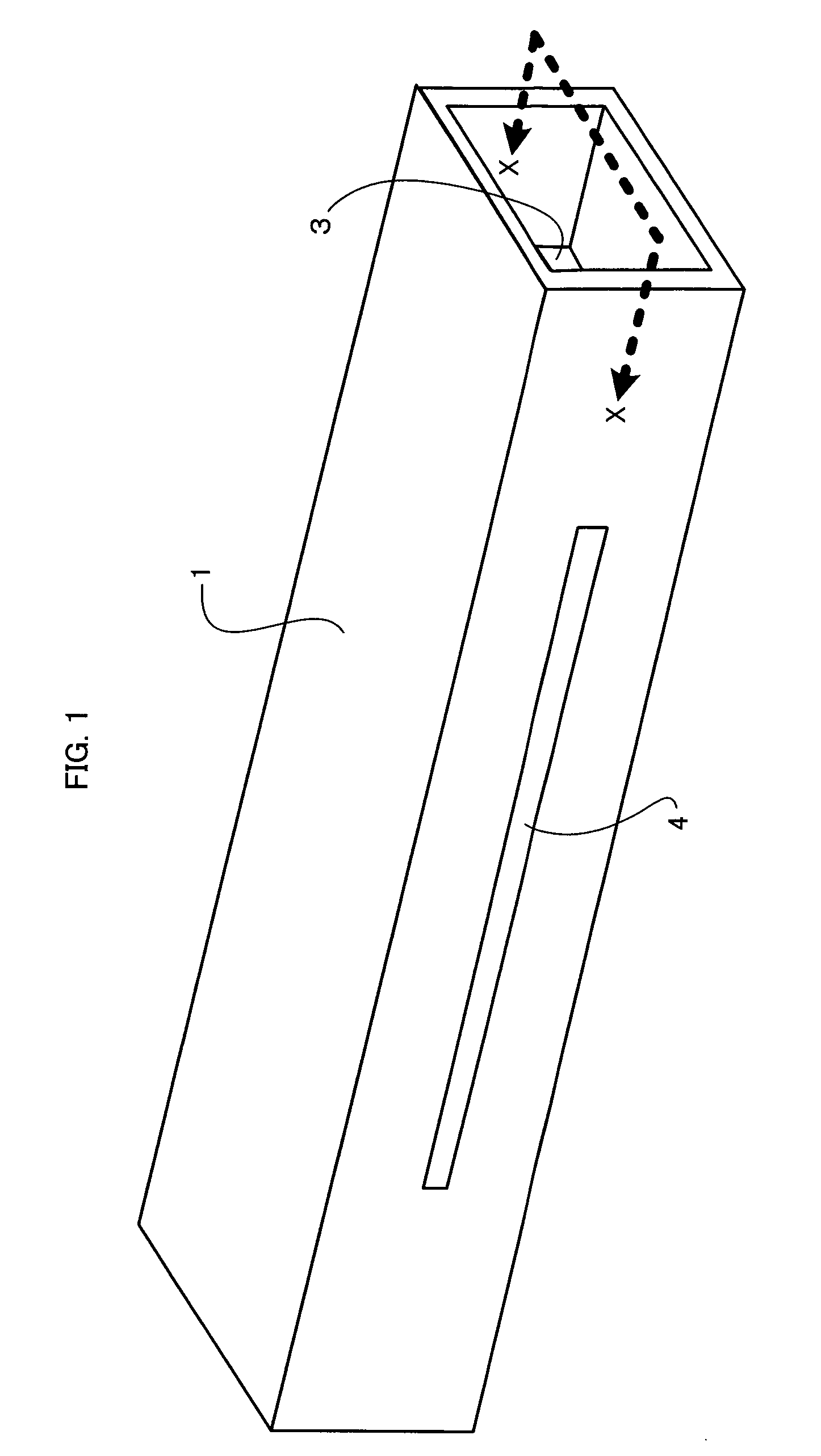
[0035]FIG. 1 is an external perspective view of a reciprocating linear actuator according to the present invention. This reciprocating linear actuator is attached to a machine tool (not shown) in such a manner that predetermined portions of the outer surface of its guide is fixed to the axis of the machine tool by using a fixing member (not shown).
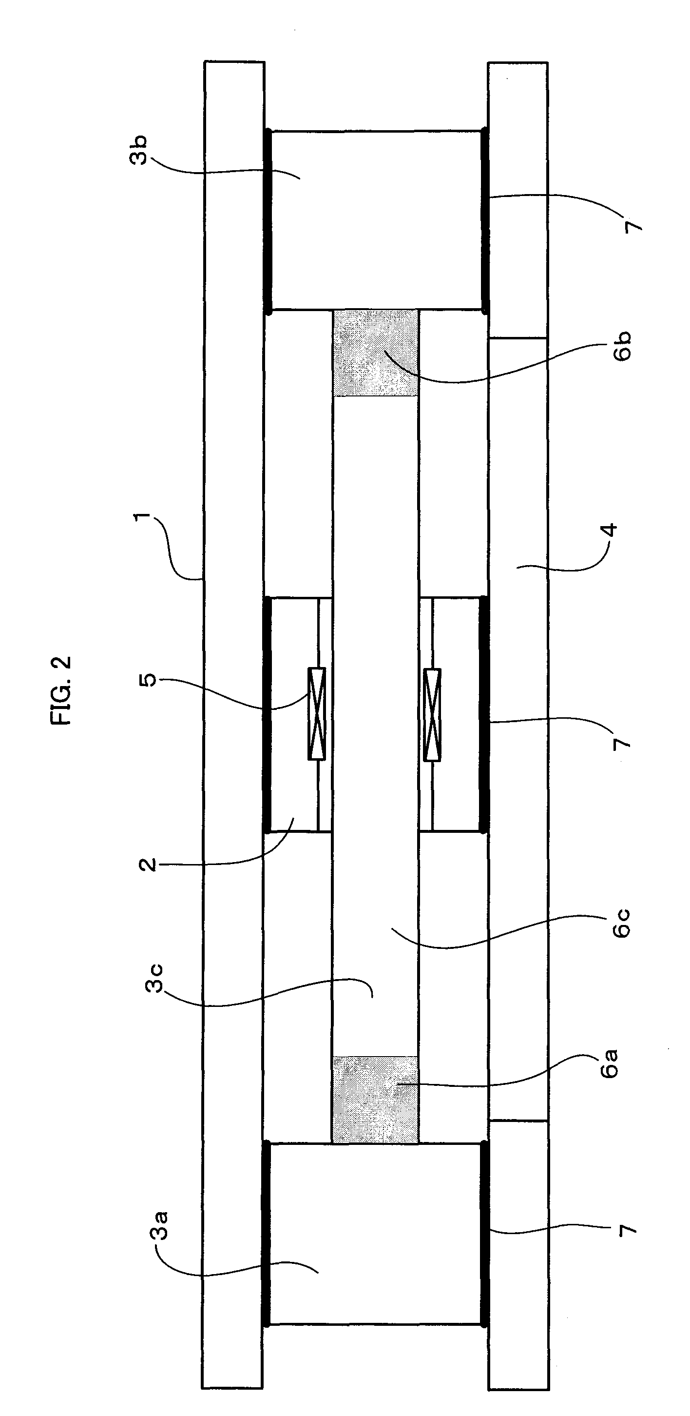
[0036]A guide 1 is in the form of a hollow box that is open at both axial ends. A slide 2 and a counter slide 3 are arranged in a hollow portion of the guide 1. In FIG. 1, a part of the counter slide 3 can be seen through one end opening of the box-like guide 1. The slide 2 and the counter slide 3 will be described in detail with reference to FIGS. 2 and 3. A slit 4 is formed in at least one side surface of the guide 1 so as to extend parallel to an axis that connects the respective centers of the opposite end openings. As shown in FIG. 7, a tool 19 that is attached to the slide 2 projects out of the guide 1 through the slit 4 and reciproc...
third embodiment
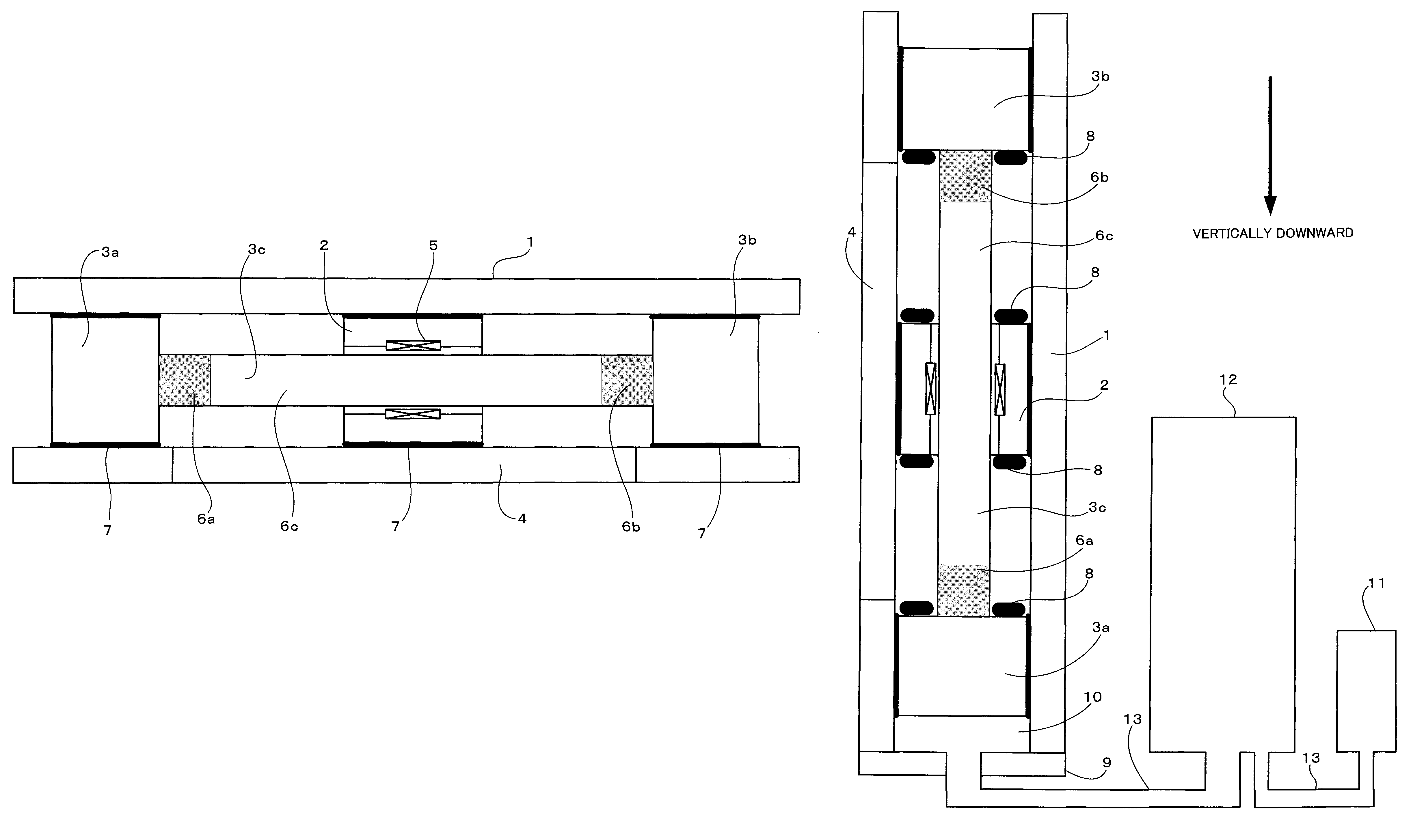
[0053]FIG. 4 is a sectional view of a reciprocating linear actuator according to the invention. The reciprocating linear actuator of this embodiment is oriented vertically.
[0054]In order to drive the reciprocating linear actuator thus oriented vertically, it is necessary to cancel the dead weight of a counter slide 3. To attain this, an air balance chamber 10 is defined in a space surrounded by the inner surface of a guide 1, an end face of a bearing portion 3a of the counter slide 3, and a lid 9 that closes one end (lower end) of the guide 1 (hollow box). The air balance chamber 10 and a pressure generator 11 are made to communicate with each other through a pipe 13 and a tank 12. As a positive pressure is generated by the pressure generator 11 to feed air into the air balance chamber 10, the internal pressure of the chamber 10 is kept positive so as to push up the counter slide 3.
[0055]If a slide 2 is reciprocated at high speed, the counter slide 3 is also reciprocated at high spe...
fourth embodiment
[0057]FIG. 5 is a sectional view of a reciprocating linear actuator according to the invention. The reciprocating linear actuator of this embodiment is oriented vertically.
[0058]In order to drive the reciprocating linear actuator thus oriented vertically, it is necessary to cancel the dead weight of a counter slide 3. To attain this, an air balance chamber 15 is defined in a space surrounded by the inner surface of a guide 1, an end face of a bearing portion 3b of the counter slide 3, and a lid 14 that closes one end (upper end) of the guide 1 (hollow box). The air balance chamber 15 and a vacuum generator 16 are made to communicate with each other through a pipe 17, and the internal pressure of the chamber 15 is made negative by the vacuum generator 16. The dead weight of the counter slide 3 can be canceled by adjusting the negative pressure to balance it by means of the vacuum generator 16.
[0059]The present embodiment in which the negative pressure is used to cancel the dead weigh...
PUM
 Abstract
Description
Claims
Application Information
 - R&D
- Intellectual Property
- Life Sciences
- Materials
- Tech Scout
- Unparalleled Data Quality
- Higher Quality Content
- 60% Fewer Hallucinations
Browse by: Latest US Patents, China's latest patents, Technical Efficacy Thesaurus, Application Domain, Technology Topic, Popular Technical Reports.
© 2025 PatSnap. All rights reserved.Legal|Privacy policy|Modern Slavery Act Transparency Statement|Sitemap|About US| Contact US: help@patsnap.com


