Double-row angular ball bearing

a ball bearing and angular contact technology, applied in the direction of rolling contact bearings, shafts and bearings, rotary bearings, etc., can solve the problems of deformation of the outer diameter surface, and deformation so as to improve the rigidity of the outer ring, and improve the circularity of the bearing ring.

Active Publication Date: 2015-10-06
NSK LTD
View PDF30 Cites 2 Cited by
  • Summary
  • Abstract
  • Description
  • Claims
  • Application Information

AI Technical Summary

Benefits of technology

[0010]According to the double-row angular contact ball bearing, one radial end portion of the sealing device is swaged and attached onto a recess arranged on the bearing ring. The ratio Ts / Tr is equal to or lower than 0.07, where Ts is thickness of the sealing device (5) and Tr is thickness of the outer ring (2) at the bottom portion of the groove (2b). Therefore, the bearing ring at a bottom portion of the recess is thick. Accordingly, since the rigidity of the bearing ring is high, the circularity of the bearing ring is hardly degraded at the time of swaging, and the circularity of the bearing ring is superior in the double-row angular contact ball bearing of the present invention.

Problems solved by technology

At the time of swaging, however, since a great force is applied onto the outer ring, the outer ring deforms and the circularity of the outer diameter surface is degraded in some cases.
In particular, when there is a small distance in a radial direction from a bottom portion of the shield groove to the outer diameter surface of the outer ring (that is a thickness of the outer ring at the bottom portion of the shield groove), the rigidity of the outer ring is low and its circularity is easily degraded.
As a result, the attachment performance might be lowered when the double-row angular contact ball bearing is attached onto the housing of a pump, or a strange noise might be generated when the double-row angular contact ball bearing rotates.

Method used


Image

  • Double-row angular ball bearing
  • Double-row angular ball bearing
  • Double-row angular ball bearing

Examples


Embodiment Construction

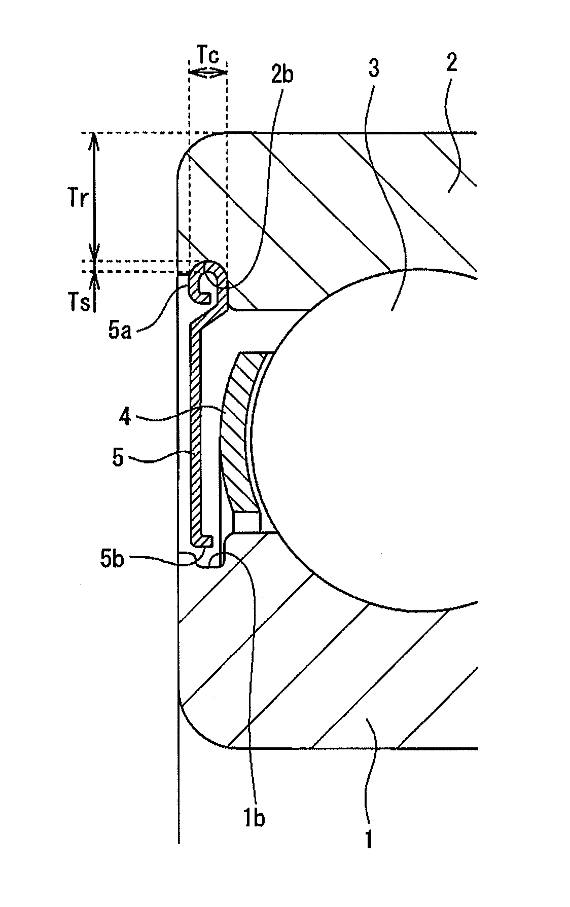
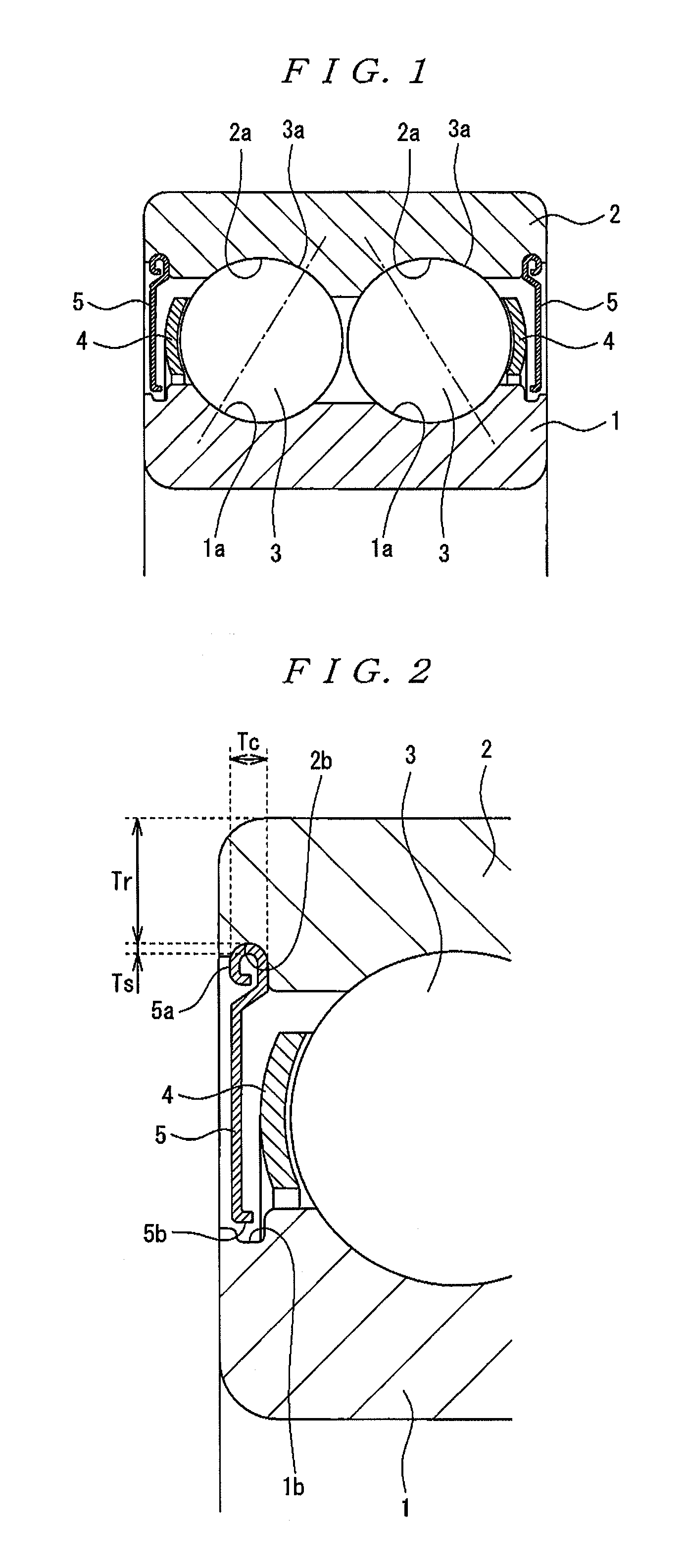
[0016]Embodiments of a double-row angular contact ball bearing according to the present invention will be described with reference to the drawings in detail. FIG. 1 is a partial vertical cross-sectional view illustrative of an embodiment of the double-row angular contact ball bearing according to the present invention. Additionally, FIG. 2 is a partial enlarged cross-sectional view of a sealing device and peripheral parts assembled into the double-row angular contact ball bearing of FIG. 1.

[0017]The double-row angular contact ball bearing of FIG. 1 is provided with: an inner ring 1; an outer ring 2; double-row balls 3 rollably arranged between raceway surfaces 1a of the inner ring 1 and raceway surfaces 2a of the outer ring 2; cages 4 each for holding balls in each row between the inner ring 1 and the outer ring 2; and non-contact sealing devices 5 each being made of a substantially disc-like member. Then, lubricant (for example, lubricating oil or grease), not illustrated, for lubr...


PUM


Abstract

A double-row angular contact ball bearing is provided with inner and outer rings, balls in two rows, a cage for holding the balls, and non-contact sealing devices made of a substantially disc-like member. Radial outer end portions of a metallic sealing device are respectively fit and swaged into grooves arranged at both axial end portions of the outer ring's inner circumferential surface. The ratio Ts / Tr is equal to or lower than 0.07, where Ts is the sealing device thickness and Tr is the outer ring thickness at the bottom portion of the groove. In addition, the ball diameter is equal to or greater than 75% of a half a bearing width to equal to or greater than 83% thereof. Furthermore, an axial width Tc of the radial outer end portion having a substantially U-shape is equal to or smaller than 2.7 mm.

Description

TECHNICAL FIELD[0001]The present invention relates to a double-row angular contact ball bearing.BACKGROUND ART[0002]A double-row angular contact ball bearing is used as a rolling bearing for rotatably supporting a rotating shaft of a submersible pump. Long life is demanded for bearings used for pumps, but a high-rated load (high-load capacity) is demanded as a bearing property for achieving the long life. As a means for increasing the high-load capacity, an increase in the diameter of the rolling element (ball) has been conventionally known (for example, see Patent Document 1).[0003]In addition, sealing performance is also demanded as the bearing property for achieving the long life. That is, a sealing device is provided in a bearing used for a pump to prevent the entrance of foreign objects or dusts from the outside to the inside thereof or leakage of lubricant from the inside to the outside thereof.[0004]As the sealing device, for example, a shield made of a steel sheet is known. ...

Claims


Application Information

Patent Timeline
Patent Type & Authority Patents(United States)
IPC IPC(8): F16C33/76F16C19/18F16C33/78
CPCF16C19/184F16C33/783F16C33/785F16C2240/40
Inventor TANABE, KOUICHISETO, TOSHIAKIABE, DAISUKE
Owner NSK LTD
Why Eureka
Try Eureka