Reciprocating linear actuator

Active Publication Date: 2010-02-25
FANUC LTD
View PDF6 Cites 21 Cited by
  • Summary
  • Abstract
  • Description
  • Claims
  • Application Information

AI Technical Summary

Benefits of technology

[0014]The object of the present invention is, for achieving the problems described above, to provide a reciprocating linear actuator in which a motion of a slide is not supported by a double bearing structure so that high bearing stiffness is ensured without a reduction in straight motion accuracy.
[0021]According to the present invention, there may be provided a reciprocating linear actuator with the above-described configuration, in which use of a double bearing structure is avoided so that high bearing stiffness is ensured without a reduction in straight motion accuracy.

Problems solved by technology

Thus, such combined straight motion accuracy tends to be poorer than a straight motion accuracy resulting from a simple structure composed of only the guide 51 and the slide 52.

Method used


Image

  • Reciprocating linear actuator
  • Reciprocating linear actuator
  • Reciprocating linear actuator

Examples


first embodiment

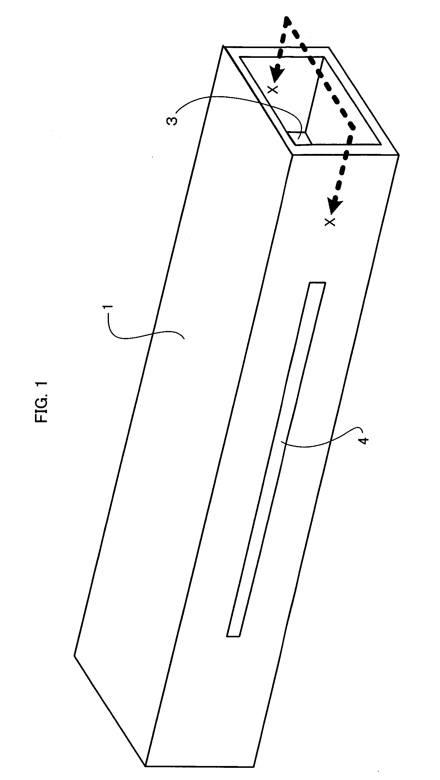
[0034]FIG. 1 is an external perspective view of a reciprocating linear actuator according to the present invention. This reciprocating linear actuator is attached to a machine tool (not shown) in such a manner that predetermined portions of the outer surface of its guide is fixed to the axis of the machine tool by using a fixing member (not shown).

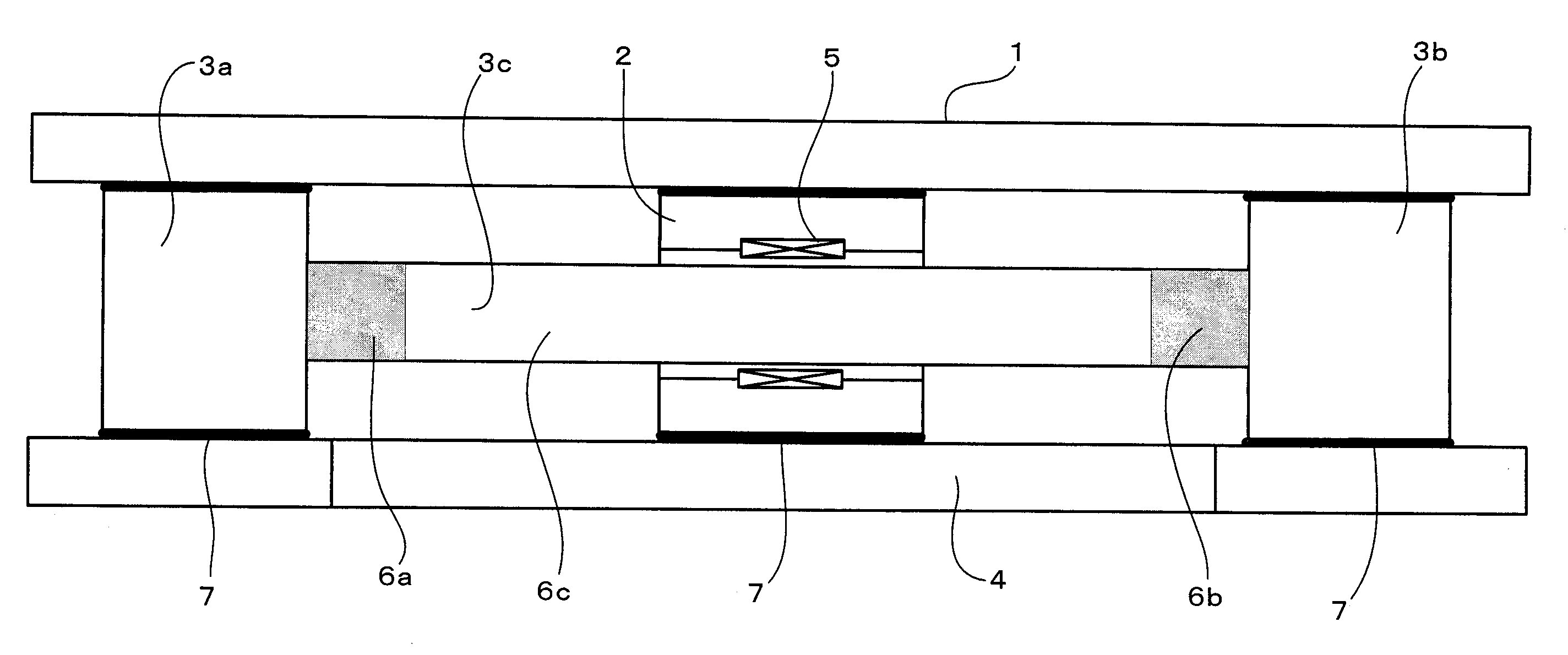
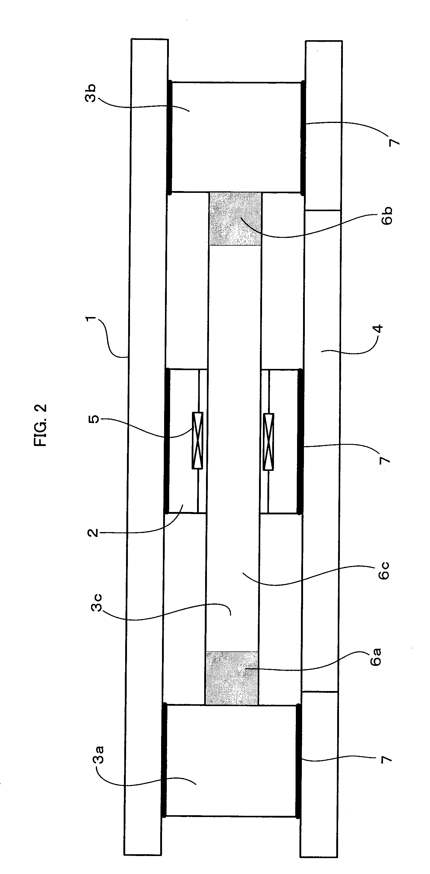
[0035]A guide 1 is in the form of a hollow box that is open at both axial ends. A slide 2 and a counter slide 3 are arranged in a hollow portion of the guide 1. In FIG. 1, a part of the counter slide 3 can be seen through one end opening of the box-like guide 1. The slide 2 and the counter slide 3 will be described in detail with reference to FIGS. 2 and 3. A slit 4 is formed in at least one side surface of the guide 1 so as to extend parallel to an axis that connects the respective centers of the opposite end openings. As shown in FIG. 7, a tool 19 that is attached to the slide 2 projects out of the guide 1 through the slit 4 and reciproc...

third embodiment

[0052]FIG. 4 is a sectional view of a reciprocating linear actuator according to the invention. The reciprocating linear actuator of this embodiment is oriented vertically.

[0053]In order to drive the reciprocating linear actuator thus oriented vertically, it is necessary to cancel the dead weight of a counter slide 3. To attain this, an air balance chamber 10 is defined in a space surrounded by the inner surface of a guide 1, an end face of a bearing portion 3a of the counter slide 3, and a lid 9 that closes one end (lower end) of the guide 1 (hollow box). The air balance chamber 10 and a pressure generator 11 are made to communicate with each other through a pipe 13 and a tank 12. As a positive pressure is generated by the pressure generator 11 to feed air into the air balance chamber 10, the internal pressure of the chamber 10 is kept positive so as to push up the counter slide 3.

[0054]If a slide 2 is reciprocated at high speed, the counter slide 3 is also reciprocated at high spe...

fourth embodiment

[0056]FIG. 5 is a sectional view of a reciprocating linear actuator according to the invention. The reciprocating linear actuator of this embodiment is oriented vertically.

[0057]In order to drive the reciprocating linear actuator thus oriented vertically, it is necessary to cancel the dead weight of a counter slide 3. To attain this, an air balance chamber 15 is defined in a space surrounded by the inner surface of a guide 1, an end face of a bearing portion 3b of the counter slide 3, and a lid 14 that closes one end (upper end) of the guide 1 (hollow box). The air balance chamber 15 and a vacuum generator 16 are made to communicate with each other through a pipe 17, and the internal pressure of the chamber 15 is made negative by the vacuum generator 16. The dead weight of the counter slide 3 can be canceled by adjusting the negative pressure to balance it by means of the vacuum generator 16.

[0058]The present embodiment in which the negative pressure is used to cancel the dead weigh...


PUM


Abstract

A reciprocating linear actuator in which a slide and a counter slide are arranged for linear movement within a hollow guide. The actuator has driving force generating means for generating a driving force between the slide and the counter slide and also has bearing structures formed individually between the guide and the slide and between the guide and the counter slide. If an external force acts on the slide, the external force is transmitted from the slide to the guide through the bearing structure between them.

Description

BACKGROUND OF THE INVENTION[0001]1. Field of the Invention[0002]The present invention relates to a reciprocating linear actuator with high bearing stiffness.[0003]2. Description of the Related Art[0004]Die sets for molding diffraction gratings and light guide plates of liquid crystal display units are expected to be formed with tens of thousands of grooves with a pitch of several microns. Cutting these numerous grooves requires both high speed and high precision. Further, the die sets for diffraction gratings and light guide plates should be free from the smallest machining errors, with the result that smooth linear drive is essential in order to prevent vibration even during high-speed operation.[0005]If a reciprocating motion is made at high speed in a conventional linear actuator, a reaction is caused by acceleration and deceleration. If machining requires a constant feed speed, in particular, the acceleration and deceleration are performed in a short stroke (i.e., in a short tim...

Claims


Application Information

Patent Timeline
IPC IPC(8): H02K33/00H02K7/08
CPCH02K41/0356
Inventor HAMURA, MASAYUKIEBIHARA, KENZO
Owner FANUC LTD
Why Eureka
Try Eureka