Spreading device for spreading out fiber filament bundles and spreading method carried out using the same

a fiber filament and spreading device technology, applied in the direction of fibre treatment, textiles and papermaking, non-woven fabrics, etc., can solve the problems of high material cost, laborious and mainly manual fabrication, high light construction potential, etc., and achieve the effect of avoiding thickening or other undetectable fiber concentrations and better embedding in the matrix

Active Publication Date: 2012-06-05
EADS DEUT GMBH
View PDF35 Cites 44 Cited by
  • Summary
  • Abstract
  • Description
  • Claims
  • Application Information

AI Technical Summary

Benefits of technology

[0019]By means of the invention a fiber filament bundle, especially a roving, can be spread especially flatly and uniformly. Thus, by using the above-mentioned method, thickenings or other undesired fiber concentrations can be avoided, and the individual filaments can be better embedded in the matrix. But the invention can be used also for other purposes where a flat and uniform spreading of fiber bundles composed of individual fibers is desired.

Problems solved by technology

A drawback is the high material costs and particularly the laborious and mainly manual fabrication.
The resulting components exhibit a very high light construction potential, but the manufacture is laborious and expensive.
However, the known processes for manufacturing preforms are complicated concerning their implementation and process technique.
Particularly for components where curved load path lines with a varying density are to be expected, it is not possible with previous processes to manufacture a correspondingly load path aligned component.
Particularly, the fibers cannot be oriented arbitrarily along defined curved paths and the fiber content cannot be locally varied.
A uniform penetration of such rovings by the material of the matrix is very complicated to accomplish.
Also, at the location of the rovings high fiber concentrations exist with only a low fiber moiety in between, so that it is difficult to vary the rate of fibers locally according to the individual requirements of the component.
If the bending is too low, the bending ratio will be too low.

Method used


Image

  • Spreading device for spreading out fiber filament bundles and spreading method carried out using the same
  • Spreading device for spreading out fiber filament bundles and spreading method carried out using the same
  • Spreading device for spreading out fiber filament bundles and spreading method carried out using the same

Examples


Embodiment Construction

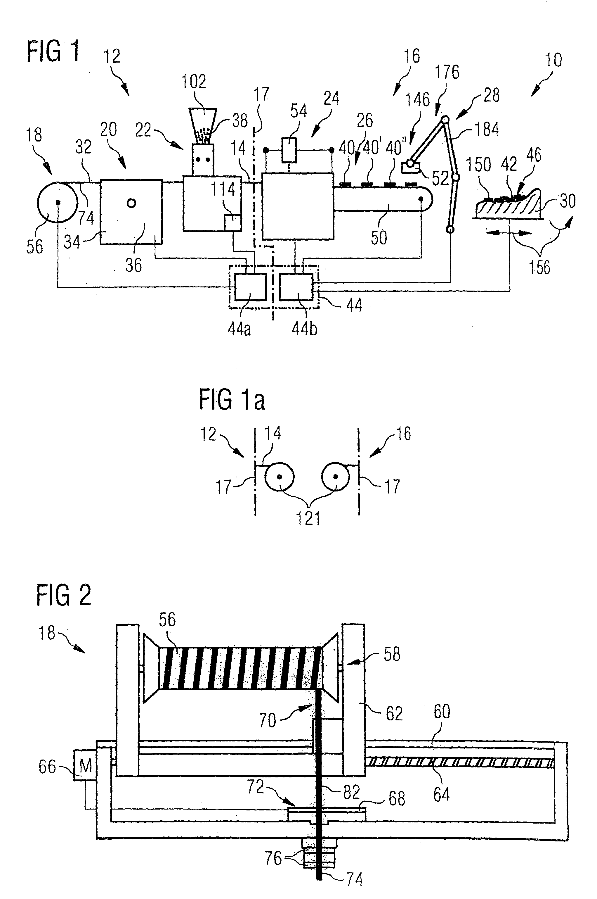
[0040]FIG. 1 shows an overall representation of a preform manufacturing device generally designated by reference number 10. This preform manufacturing device allows the fabrication of a complicated textile semi-product with load path aligned fiber filaments for manufacturing fiber composite structures in an easy manner even if the semi-product has a complicated structure. Such textile semi-products are called preforms. The fabrication of these preforms takes place from individual short fiber pieces that are fixed with a binder material and cut off from a specially prepared strand of fiber filaments or fiber band. Accordingly, the preform manufacturing device can divided up into a preparation module 12 for the possible preparation of the fiber bind 14 and a cutting and laying module 16 for cutting-off and laying the fiber band pieces. A possible separation 17 between these module 12 and 16 is indicated by a chain line.

[0041]FIG. 1 illustrates a first embodiment of such a cutting and ...


PUM

PropertyMeasurementUnit
widthaaaaaaaaaa
widthaaaaaaaaaa
widthaaaaaaaaaa

Abstract

A spreading device (20) for spreading a fiber filament bundle (32) to form a flat fiber band (14) has at least one convexly bent spreading edge (80) that is movable. The convexly bent spreading edge has at least one direction component perpendicular to a longitudinal extension of the fiber filament bundle (32) to be spread relative to the convexly bent spreading edge. The fiber filament bundle is configured to be placed under tension onto the convexly bent spreading edge (80) and thereafter is configured to be moved again with the at least one direction component perpendicular to the fiber filament bundle (32) away from the fiber filament bundle to release the fiber filament bundle from the convexly bent spreading edge (80).

Description

CROSS-REFERENCE TO RELATED APPLICATIONS[0001]This U.S. National stage application claims priority under 35 U.S.C. §119(a) to German Patent Application No. 10 2007 012 607.9, filed in Germany on Mar. 13, 2007, the entire contents of which are hereby incorporated herein by reference.BACKGROUND OF THE INVENTION[0002]1. Field of the Invention[0003]The invention relates to a spreading device to spread fiber filament bundles to form a flat fiber band. The spreading device according to the present invention is particularly suited for use in a method for manufacturing a preform for a load path aligned fiber composite structure. Moreover, the invention relates to a spreading method carried out using such a spreading device.[0004]2. Background Information[0005]At the construction of vehicles of all kinds, particularly at the construction of aircrafts and spacecrafts, but also in other branches of industry such as mechanical engineering, there is an increasing need for strong and yet lightweig...

Claims


Application Information

Patent Timeline
Patent Type & Authority Patents(United States)
IPC IPC(8): D02J1/18D04H3/002D04H3/04D04H3/12
CPCD02J1/18D04H3/002D04H3/04D04H3/12
Inventor MEYER, OLIVER
Owner EADS DEUT GMBH
Why Eureka
Try Eureka