Measuring instrument

a technology of measuring instruments and measuring parts, applied in the field of measuring instruments, can solve the problem that the contact piece cannot be easily moved from the object, and achieve the effect of reducing the measuring for

Active Publication Date: 2012-06-05
MITUTOYO CORP
View PDF5 Cites 5 Cited by
  • Summary
  • Abstract
  • Description
  • Claims
  • Application Information

AI Technical Summary

Benefits of technology

[0010]An object of the invention is to provide a measuring instrument capable of improving high-speed responsivity and measuring accuracy without impairing stability of a feedback controller.
[0012]According to the aspect of the invention, the controller includes the feedback compensator for feedback compensation in accordance with the measuring force. Accordingly, the measuring force outputted from the feedback compensator (hereinafter referred to as a compensation measuring force) can be adjusted so that the contact piece is not easily moved away from the object during measurement. The controller further includes the feedback controller for feedback control of the moving mechanism based on the deviation between the compensation measuring force and the target value outputted from the target value output. Accordingly, the contact piece is not easily moved away from the object even when high-speed responsivity is required for the feedback controller. Thus, the measuring instrument can improve high-speed responsivity and measuring accuracy without impairing stability of the feedback controller.
[0015]Therefore, even when high-speed responsivity is required for the feedback controller, the contact piece is not easily spaced away from the object during measurement. Thus, the measuring instrument can improve high-speed responsivity without impairing stability of the feedback controller.
[0017]According to the above arrangement, the feedback compensator performs the feedback compensation to decrease the deviation between the compensation measuring force and the target value when the measuring force detected by the measuring detector is larger than the target value. Accordingly, the moving mechanism is controlled to decrease the measuring force detected by the measuring force detector. Therefore, even when the contact piece is suddenly bounced up due to the geometry variation of the object, the measuring force is not excessively changed, so that a control command for moving the contact piece excessively away from the object is not supplied. Thus, the contact piece is not easily moved away from the object.

Problems solved by technology

Accordingly, the contact piece is not easily moved away from the object even when high-speed responsivity is required for the feedback controller.

Method used


Image

  • Measuring instrument
  • Measuring instrument
  • Measuring instrument

Examples


first exemplary embodiment

[First Exemplary Embodiment]

[0025]A first exemplary embodiment of the invention will be described below with reference to the accompanying drawings.

[Overall Arrangement of Surface Texture Measuring Instrument]

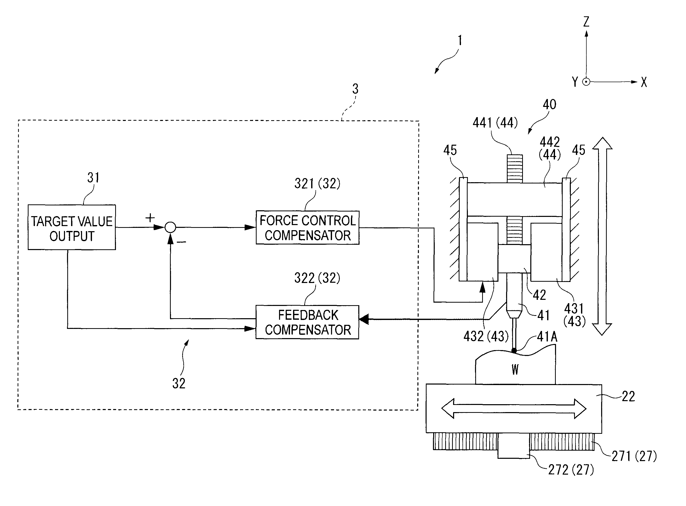
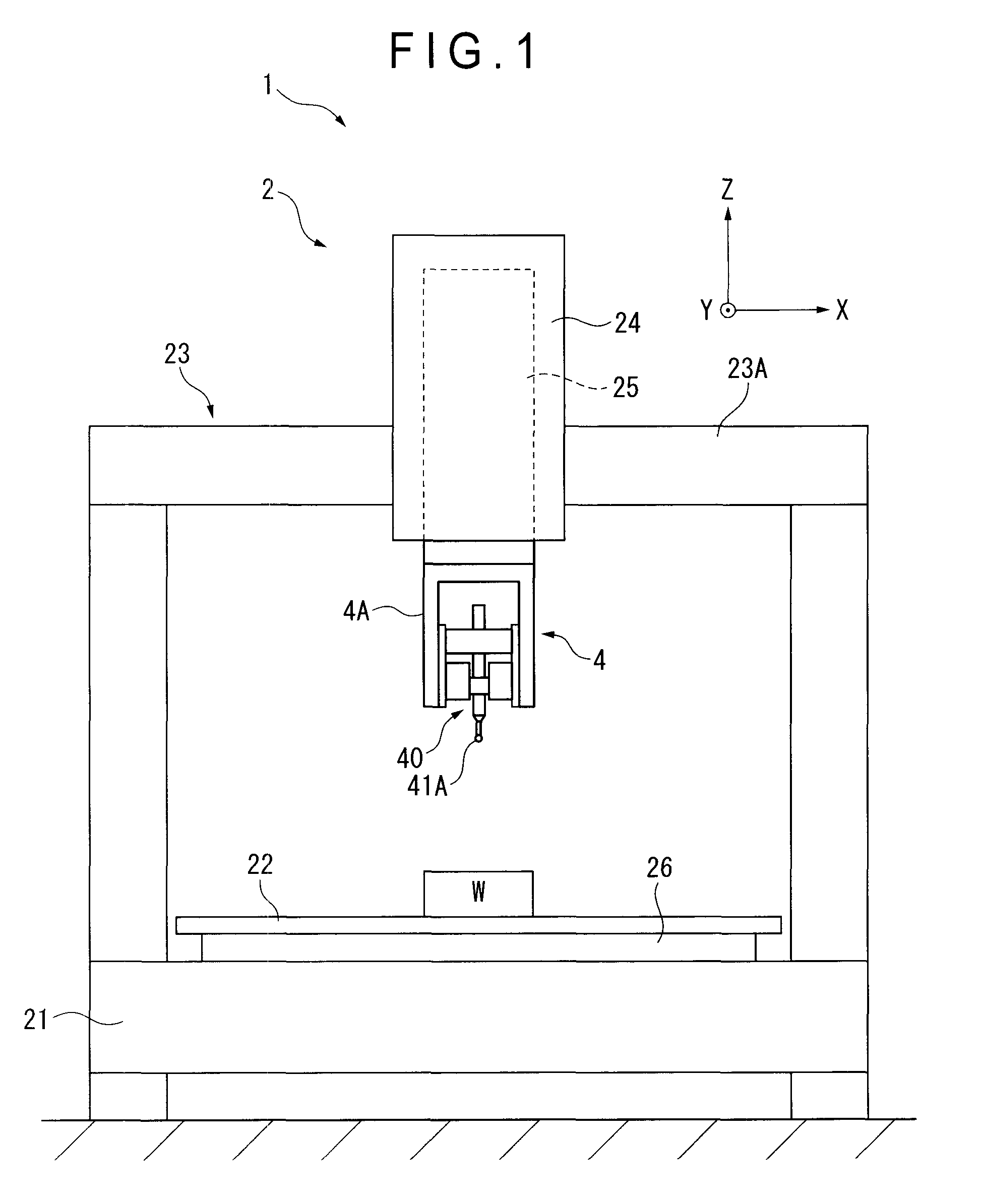
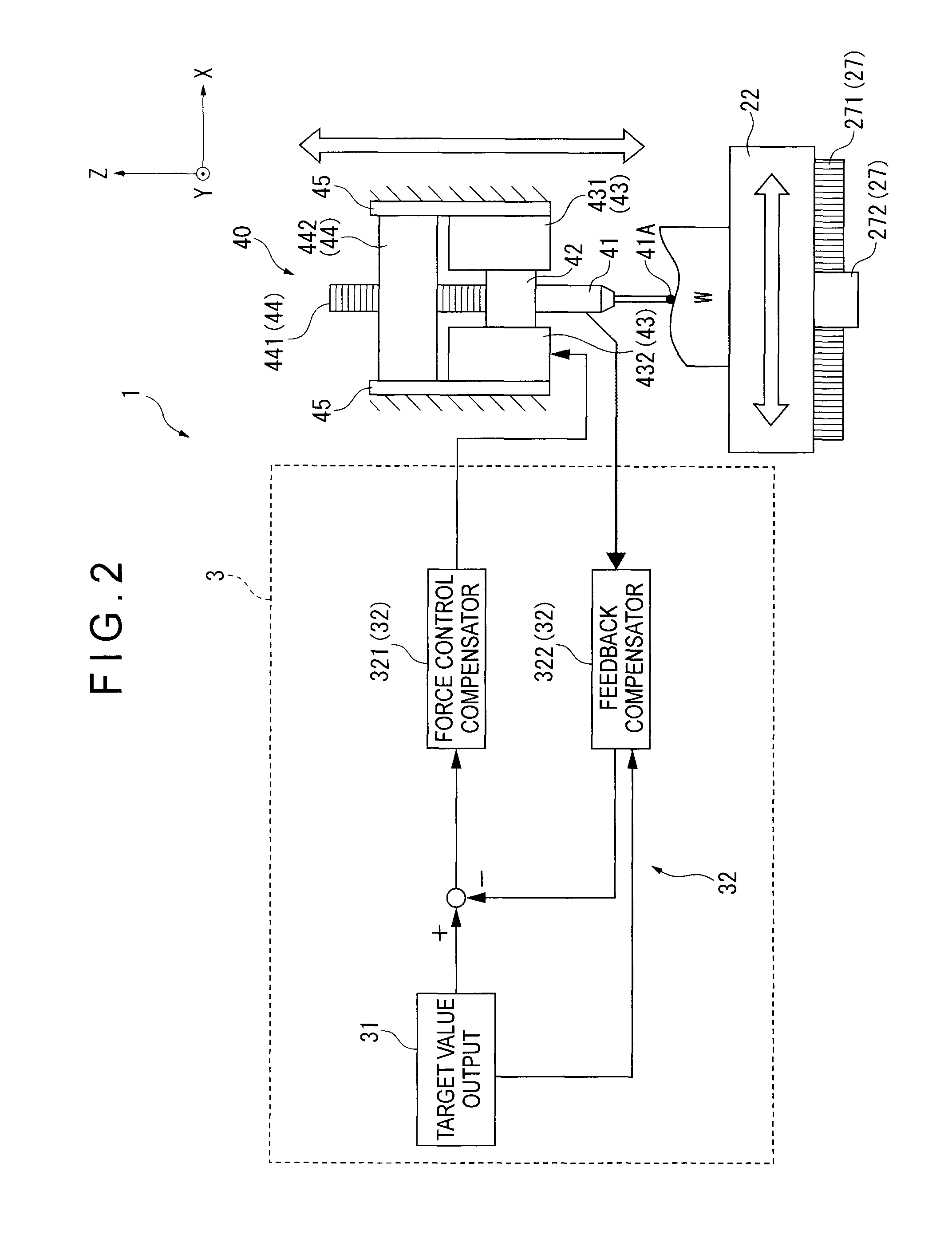
[0026]FIG. 1 is a front view of a surface texture measuring instrument 1 according to a first exemplary embodiment of the invention. FIG. 2 is a block diagram schematically showing the surface texture measuring instrument 1. Incidentally, in FIGS. 1 and 2, an upper direction on the paper surface is referred to as a +Z-axis direction, two axes orthogonal to the Z-axis are respectively referred to as an X-axis (parallel to the paper surface) and a Y-axis (orthogonal to the paper surface). The same applies to the other figures.

[0027]The surface texture measuring instrument 1 (serving as a measuring instrument) includes a measuring instrument body 2 as shown in FIG. 1 and a controller 3 that controls the measuring instrument body 2 (see FIG. 2). The controller 3 will be described i...

second exemplary embodiment

[Second Exemplary Embodiment]

[0056]A second exemplary embodiment of the invention will be described below with reference to the accompanying drawings.

[0057]FIG. 6 shows a relationship between the measuring force and the compensation measuring force. FIG. 7 shows a relationship between the measuring force and the deviation of the measuring force relative to the target value.

[0058]In the first exemplary embodiment, the compensation factors C1 and C2 are set to be two. In contrast, in the second exemplary embodiment, the compensation factor C1 is set to be one and the compensation factor C2 is set to be two.

[0059]It should be noted that components which are identical or correspond to those of the first exemplary embodiment will be denoted by the same reference numerals, description of which will be omitted.

[0060]When the feedback compensator 322 determines that the measuring force is larger than the target value R (a direction shown by an arrow A in FIGS. 6 and 7), the feedback compens...


PUM


Abstract

A surface texture measuring instrument includes a contact piece to be in contact with an object, a sensor driving mechanism that moves the contact piece along the surface of the object, a controller that controls the sensor mechanism, and a force sensor that detects a measuring force exerted on the contact piece when the contact piece is brought into contact with the object. The controller includes a target value output that outputs a target value of the measuring force, a feedback controller that performs feedback control of the sensor driving mechanism based on a deviation between the measuring force and the target value, and a feedback compensator provided on the feedback controller. The feedback compensator performs feedback compensation in accordance with the measuring force.

Description

[0001]The entire disclosure of Japanese Patent Application No. 2008-172334, filed Jul. 1, 2008, is expressly incorporated by reference herein.BACKGROUND OF THE INVENTION[0002]1. Field of the Invention[0003]The present invention relates to a measuring instrument, and more particularly to a measuring instrument having a contact piece to be in contact with an object to be measured.[0004]2. Description of Related Art[0005]There has been known a measuring instrument which includes a contact piece to be in contact with an object to be measured, a moving mechanism that moves the contact piece along a surface of the object to be measured, and a controller that controls the moving mechanism (for example, see Document 1: JP-A-2007-309684).[0006]A coordinate measuring instrument disclosed in Document 1 includes a probe (contact piece), a relative moving mechanism (moving mechanism), a controller, and a force sensor (measuring force detector) that detects a measuring force exerted on the probe ...

Claims


Application Information

Patent Timeline
Patent Type & Authority Patents(United States)
IPC IPC(8): G01B5/26
CPCG01B3/008
Inventor IGASAKI, SHIROYAMAGATA, MASAOKI
Owner MITUTOYO CORP
Why Eureka
Try Eureka