Fiber application machine comprising a flexible compacting roller with a thermal regulation system

a technology of thermal regulation system and fiber application machine, which is applied in the direction of document inserters, roof tools, decorative arts, etc., can solve the problems of unsatisfactory thermoplastic resin implementation, difficult to design and make, and complex structure of such segmented metallic rollers, and achieve uniform compacting of applied bands, design and making easy

Active Publication Date: 2012-06-05
CORIOLIS GRP
View PDF121 Cites 25 Cited by
  • Summary
  • Abstract
  • Description
  • Claims
  • Application Information

AI Technical Summary

Benefits of technology

[0014]The present invention is aimed to provide a solution overcoming the aforementioned drawbacks, particularly making it possible to implement a wide variety of resins, ranging from thermosetting to thermoplastic ones, with a substantially uniform compacting of the applied band and which can be designed and made easily.
[0023]In the case of a thermal regulation fluid at room temperature, at, for example, between 15° C. and 30° C., or cooled at a temperature lower than 15° C., the circulation of the thermal regulation fluid in the compacting roller makes it possible to cool the compacting roller on the surface, as well as over the thickness of the flexible material cylinder and thus makes it possible to use a stable, flexible material compacting roller which can be used for the application of fibers pre-impregnated with resins, particularly, thermoplastic resins. The machine according to the invention, which comprises a compacting roller of simple design, makes it possible to use a wide variety of thermosetting or thermoplastic resins in combination with a wide range of synthetic or natural, hybrid or non-hybrid fibers, particularly, fibers usually used in the composite field, such as glass fibers, carbon, quartz, and aramid fibers.
[0026]According to one embodiment, the fluid communication system includes longitudinal grooves opening onto the cylinder lateral sides, the radial channels opening onto the longitudinal grooves. So as to achieve a better distribution of the thermal regulation fluid flux on the external surface, the fluid communication system advantageously includes circular grooves onto which the radial channels open.
[0028]According to one embodiment, the fluid communication system comprises a sheath covering the external surface of the cylinder, the sheath being made of a porous material, thus making it possible to discharge the thermal regulation fluid by the lateral sides of the sheath. The porous material is made, for example, of an open cell-type thermoplastic and / or elastomeric foam, or a non-woven fiber material. The porous material of the sheath is elastically deformable so as to conform to the cylinder deformation during the fiber application, but exhibits a lower elasticity than that of the flexible, and possibly porous, material constituting the cylinder so as to allow for the discharging of the thermal regulation fluid.
[0030]This shielding sheath makes it possible to avoid the heat build-up of the compacting roller over the entire thickness thereof owing to the heat radiation of the heating system directed towards the compacting roller. This shielding sheath absorbs and / or reflects the heat radiation, the thermal regulation fluid thus serving for the cooling of this shielding sheath so as to avoid a heat build-up, by conduction, of the cylinder.
[0031]In the case of fiber placement, the machine typically includes a cutting assembly making it possible to individually cut the fibers upstream of the compacting roller and rerouting assembly, disposed upstream of the cutting means, for rerouting each fiber that has just been cut towards the compacting roller so as to be able to stop and resume the band application at any time, as well as varying the applied band width. When the width of the applied band is reduced, for example, of only 10 fibers for a 16 or 32 fibers-type placement head, the roller directly receives the heat radiation, with no fibers interposed between the heat source and the roller. The shielding sheath makes it possible to avoid the high heat build-up due to this direct heat radiation.

Problems solved by technology

Nevertheless, the structure of such segmented metallic rollers and their implementation proved to be complex.
Nevertheless, theses rollers proved to be unsatisfactory for the implementation of thermoplastic resins.
Moreover, the heating of the bands deposited beforehand for their adhesion through welding to the newly applied band is only made through thermal conduction, which constitutes a restrictive factor for the fiber application speed.

Method used


Image

  • Fiber application machine comprising a flexible compacting roller with a thermal regulation system
  • Fiber application machine comprising a flexible compacting roller with a thermal regulation system
  • Fiber application machine comprising a flexible compacting roller with a thermal regulation system

Examples


Embodiment Construction

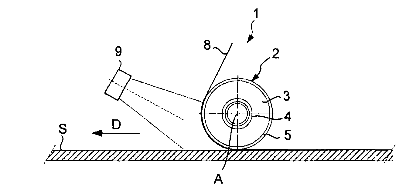
[0048]With reference to FIG. 1, the fiber application machine comprises an application head 1 for applying a band 8 of resin pre-impregnated fibers, said head including a compacting roller 2 which is rotationally mounted about an axis A on a support structure (not shown) of the head, the head being mounted by said support structure at the end of a moving system, for example, a robot wrist-joint.

[0049]The head further comprises a heating system 9 also mounted on the support structure upstream of the roller with regard to the progress direction D of the application head during the application of fiber band 8 on an application surface S. For example, the heating device is a laser type heating system, of which radiation is directed towards the band, just before the compacting thereof, as well as towards the band or bands deposited beforehand. As illustrated in FIG. 1, the radiation is thus obliquely directed towards the roller so as to heat a band section disposed on the roller, before ...


PUM

PropertyMeasurementUnit
temperatureaaaaaaaaaa
temperaturesaaaaaaaaaa

Abstract

A fiber application machine for the production of parts made of composite materials comprising a compacting roller for applying on an application surface a band formed of at least a resin pre-impregnated flat fiber, and a heating system able to emit a heat radiation towards the band. The compacting roller comprises a rigid central tube provided with radial holes, and a cylinder made of an elastically deformable, flexible material, assembled on the central tube, and having a fluid communication assembly that brings the radial holes into fluid communication with the external surface of the cylinder. The machine includes a thermal regulation system that injects a thermal regulation fluid in the central tube internal passage.

Description

RELATED APPLICATION[0001]The present application claims priority to French Application No. 09 54963 filed Jul. 17, 2009, which is incorporated herein in its entirety by reference.TECHNICAL FIELD[0002]The present invention relates to a fiber application machine for the production of parts made of composite materials, and more particularly, such a machine comprising a fiber heating system and a heat-resistant compacting roller.BACKGROUND ART[0003]There have been known fiber application machines, for applying on an application surface of a male or female mold, a wide band formed of at least a ribbon-type resin pre-impregnated flat fiber, particularly carbon fibers pre-impregnated with a thermoplastic or thermosetting resin, and particularly so-called fiber placement machines for applying a wide band formed of a plurality of resin pre-impregnated fibers.[0004]These fiber placement machines, such as described in patent document WO2006 / 092514 typically comprise a fiber placement head and ...

Claims


Application Information

Patent Timeline
Patent Type & Authority Patents(United States)
IPC IPC(8): B65H81/00
CPCB29C70/384F28F5/02Y10T156/1348Y10T156/1788B30B3/005
Inventor HAMLYN, ALEXANDERHARDY, YVAN
Owner CORIOLIS GRP
Why Eureka
Try Eureka