Single-motor massager

a single-motor, massager technology, applied in the field of massage, can solve the problems of high prime cost of body massager, complex manufacturing process of conventional body massager, and many and complicated components of conventional body massager, and achieve the effect of enhancing the performance of massaging motion and reducing the prime cos

Inactive Publication Date: 2012-06-05
HUANG CHIEN MING
View PDF6 Cites 2 Cited by
  • Summary
  • Abstract
  • Description
  • Claims
  • Application Information

AI Technical Summary

Benefits of technology

[0007]The main objective of the present invention is to provide a single-motor massager to decrease the prime cost and enhance the performance of the massaging motion.
[0011]When a user turns on the single-motor massager, the motor rotates the main massaging device of the massage assembly to provide the user a massage function. Furthermore, the main gear drive of the massage assembly drives the gear shaft assembly to move along the two gear racks on the base. Therefore, the single-motor massager provides a large area massage function. Because the gear racks are in pair and set equally, the gear shaft assembly moves along the gear racks smoothly and stably. Moreover, only one motor and simplified gear drives are needed, the manufacturing process of the massager is simplified and the cost of the massager is reduced.

Problems solved by technology

However, the conventional body massager needs to have many and complicated components to move the massage assembly.
Due to the complexities of the conventional body massager, the manufacturing process of the conventional body massager is complicated and the prime cost of the body massager is high.
Therefore, the conventional body massager needs a complicated guide system to stable the movement of the massage assembly.
Thus, the complicated guide system also needs complicated manufacturing process and costs high.

Method used


Image

  • Single-motor massager
  • Single-motor massager
  • Single-motor massager

Examples


Embodiment Construction

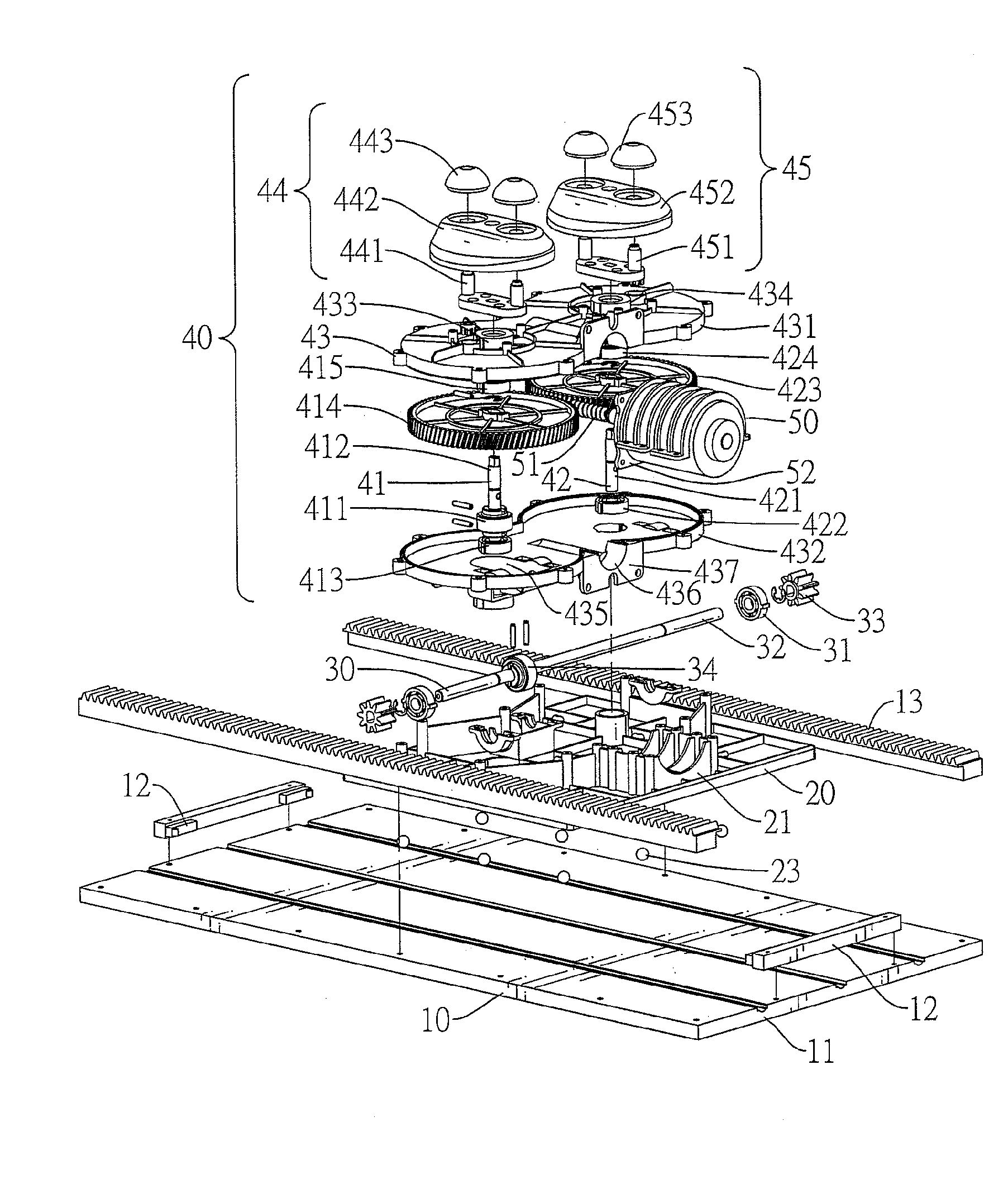
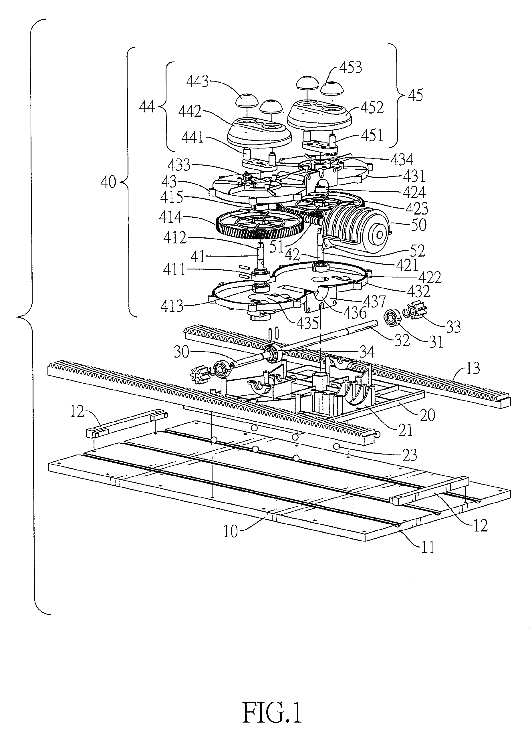
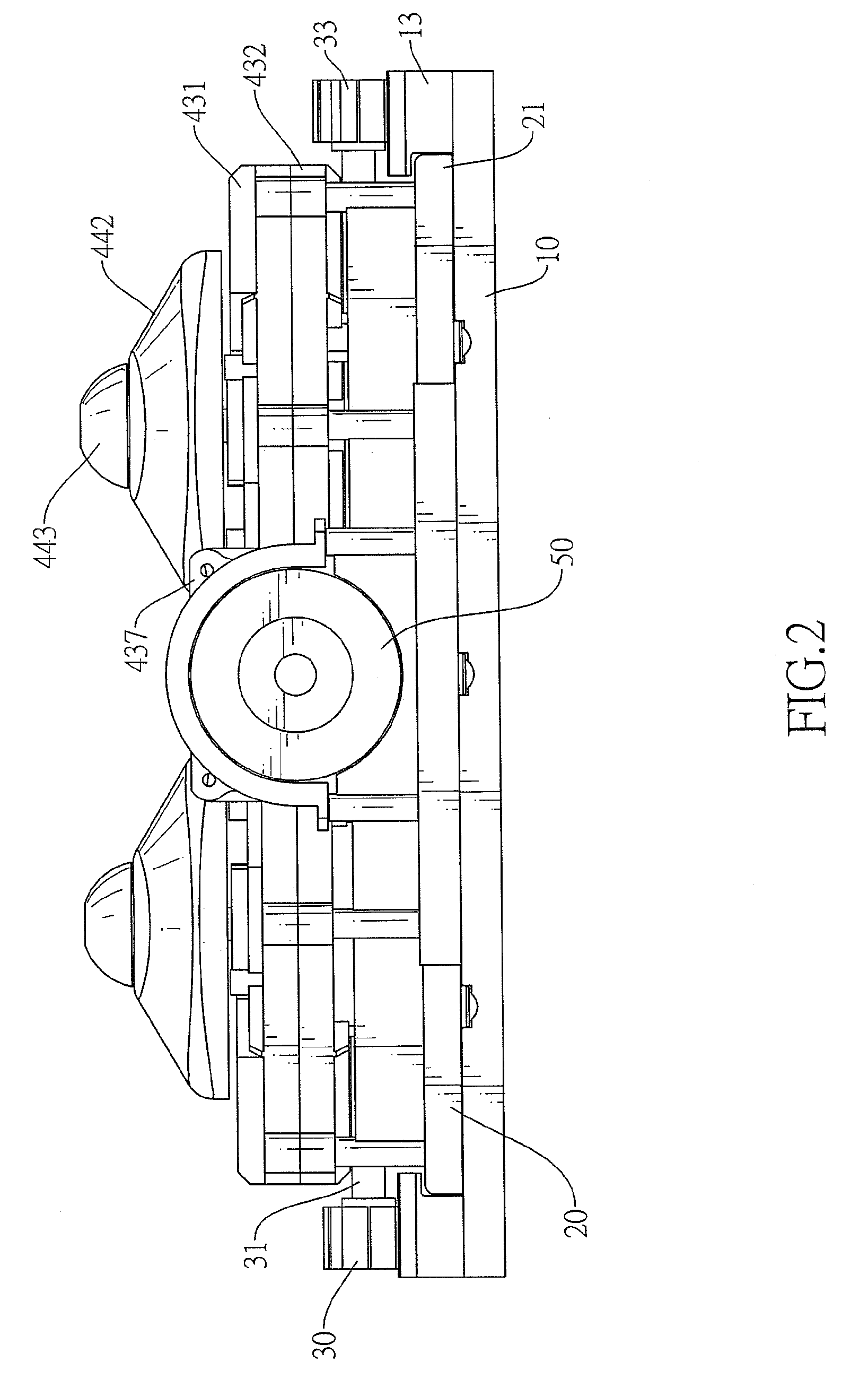
[0025]With reference to FIGS. 1, 2, 5 and 7, a single-motor massager in accordance with the present invention comprises a base (10), a carriage (20), a gear shaft assembly (30), a massage assembly (40), a motor (50) and an outer cover (60).

[0026]With reference to FIGS. 1, 2 and 8, the base (10) has a top surface, multiple grooves (11), two reverse switches (12), a middle switch (121) and two gear racks (13). The top surface has two ends and two sides. The grooves (11) are formed in the top surface of the base (10) and are parallel to each other grooves (11). The reverse switches (12) are mounted securely on the base (10) and are mounted respectively on the two ends of the top surface of the base (10). The middle switch (121) is mounted on the top surface of the base (10) and is mounted between the reverse switches (12). The gear racks (13) are mounted respectively on the two sides of the top surface of the base (10) and are parallel to the grooves (11).

[0027]With further reference t...


PUM


Abstract

A single-motor massager has a base, a carriage, a gear shaft assembly, a massager assembly and a motor. The base has two gear racks. The carriage is mounted movably on the base. The gear shaft assembly is mounted on the carriage and is mounted movably on the gear racks of the base. The massaging assembly is mounted on the carriage and connects to the gear shaft assembly. The motor drives the massaging assembly of the massager assembly to provide massaging function and to move the carriage and the gear shaft assembly and the massaging assembly along the base. With the two gear racks, the massaging assembly moves stably. With only one motor and the simplified gear shaft assembly and massager assembly, the manufacturing process of the massager is simplified and the cost of the massager is reduced.

Description

BACKGROUND OF THE INVENTION[0001]1. Field of the Invention[0002]The present invention relates to a massager, particularly to a single-motor massager having a simplified structure.[0003]2. Description of the Prior Arts[0004]Body massagers are widely used to massage the users to make the users feel relax and comfortable. A conventional body massager has a massage assembly moving back and forth to massage a wide area of the body of the user. However, the conventional body massager needs to have many and complicated components to move the massage assembly. Due to the complexities of the conventional body massager, the manufacturing process of the conventional body massager is complicated and the prime cost of the body massager is high.[0005]Furthermore, to provide a larger-ranged massage function, the conventional body massager requires two motors. One of the motors moves the massage assembly back and forth, and the other one of the motors provides the massage function. Therefore, the c...

Claims


Application Information

Patent Timeline
Patent Type & Authority Patents(United States)
IPC IPC(8): A61H19/00
CPCA61H7/003A61H2201/0149A61H2201/1669
Inventor HUANG, CHIEN-MING
Owner HUANG CHIEN MING
Why Eureka
Try Eureka