Fuel cell stack with power collecting terminals

a fuel cell and terminal technology, applied in the field of fuel cell stacks, can solve the problems of large number of components, high cost, and low current collection performance through the electrode pole b>6/b>, and achieve efficient and economic terminal production, good current collection performance, and simple steps and structure

Active Publication Date: 2012-06-05
HONDA MOTOR CO LTD
View PDF12 Cites 2 Cited by
  • Summary
  • Abstract
  • Description
  • Claims
  • Application Information

AI Technical Summary

Benefits of technology

[0009]The present invention has been made to solve the problems of this type, and an object of the present invention is to provide a fuel cell stack and a method of producing a terminal for the fuel cell stack in which, with simple steps and structure, it is possible to efficiently and economically produce the terminal having good current collection performance.
[0015]By the friction stir welding, flatness in the joint portion is improved, and it becomes possible to integrally join the electrically conductive plate member and the electrically conductive rod terminal suitably and reliably. Thus, the joined state of the terminal is suitably maintained, and the contact resistance can be reduced advantageously.
[0016]Further, reduction in the number of components can be achieved, and the terminals can be produced economically. Moreover, for example, in comparison with the case where the electrically conductive plate member and the electrically conductive rod terminal are fabricated into one piece by cutting, significant cost reduction is achieved. For example, in comparison with the case of adopting pressure forming, damages of the components can be reduced as much as possible.

Problems solved by technology

However, in the above structure where the electrode pole 6 is simply connected to the terminal plate 3, the contact state tends to vary, and the current collection performance through the electrode pole 6 may be lowered undesirably.
Further, since the electrode pole 6 is inserted into the insulating sleeve 7, and fixed through the nut 8, the assembling operation is laborious, and a large number of components are required.

Method used


Image

  • Fuel cell stack with power collecting terminals
  • Fuel cell stack with power collecting terminals
  • Fuel cell stack with power collecting terminals

Examples


Embodiment Construction

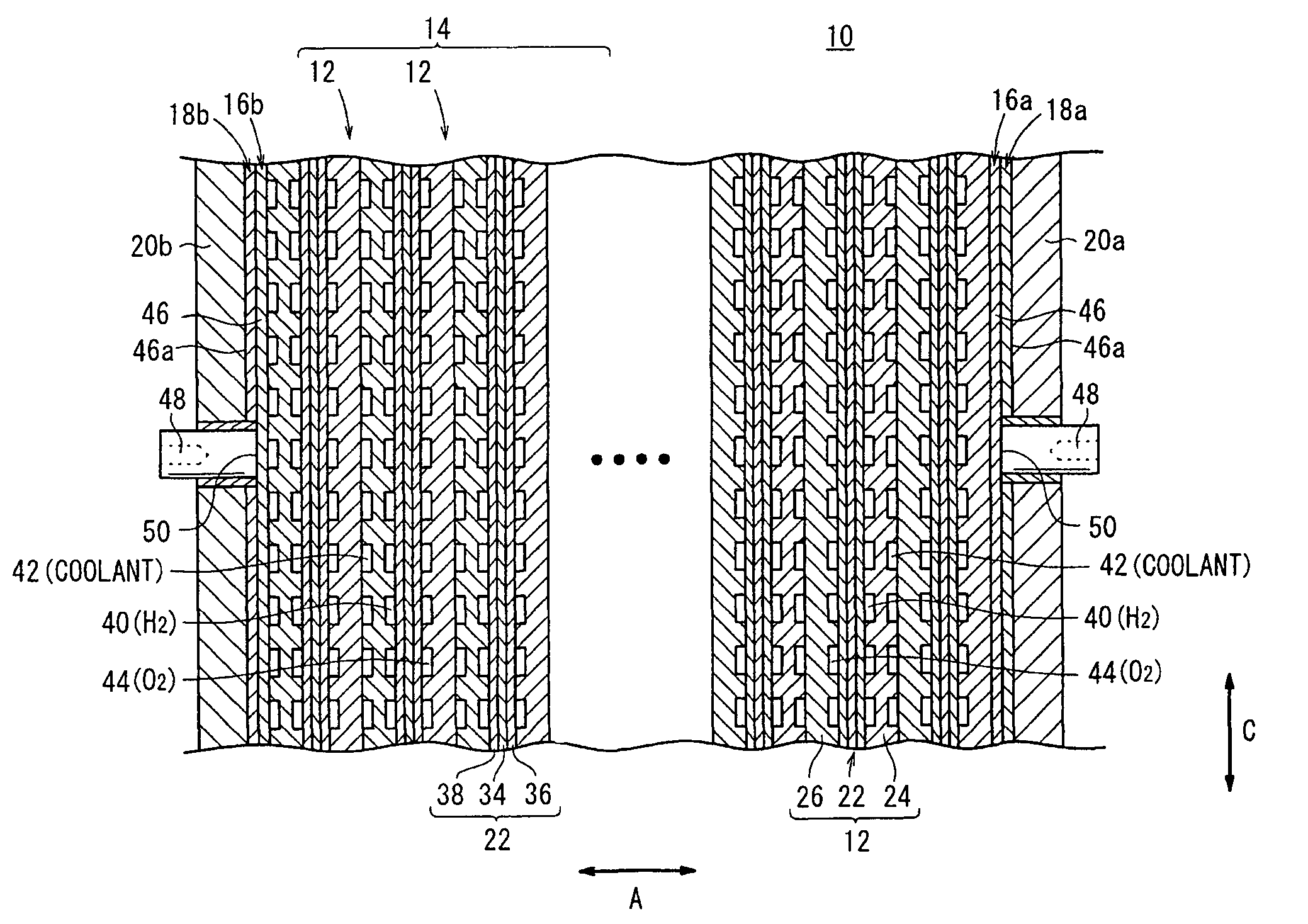
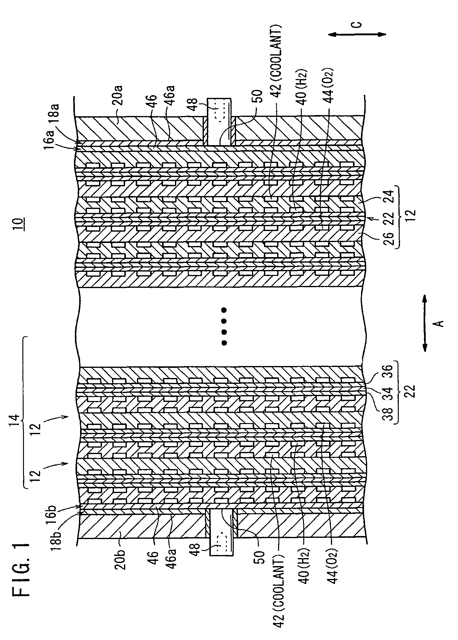
[0025]As shown in FIG. 1, a fuel cell stack 10 according to an embodiment of the present invention has a stack body 14 formed by stacking a plurality of power generation cells 12 in a horizontal direction indicated by an arrow A. A terminal 16a is provided at one end of the stack body 14 in the stacking direction indicated by the arrow A. An insulating plate 18a is provided outside the terminal 16a, and an end plate 20a is provided outside the insulating plate 18a. A terminal 16b is provided at the other end of the stack body 14 in the stacking direction. An insulating plate 18b is provided outside the terminal 16b, and an end plate 20b is provided outside the insulating plate 18b. Components between the end plates 20a, 20b are tightened together through a plurality of tie rods (not shown).

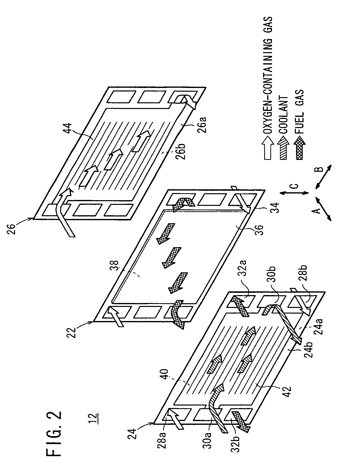
[0026]As shown in FIG. 2, each of the power generation cells 12 includes a membrane electrode assembly 22 and first and second separators 24, 26 sandwiching the membrane electrode assembly 22. The...


PUM

PropertyMeasurementUnit
electrically conductiveaaaaaaaaaa
thicknessaaaaaaaaaa
electrical energyaaaaaaaaaa

Abstract

A fuel cell stack includes a stack body formed by stacking a plurality of power generation cells. A terminal, an insulating plate, and an end plate are provided at one end of the stack body, and a terminal, an insulating plate, and an end plate are provided at the other end of the stack body. Each of the terminals includes an electrically conductive plate member, and an electrically conductive rod terminal joined integrally with the electrically conductive plate member. A joint portion joining the electrically conductive plate member and the electrically conductive rod terminal is formed by friction stir welding.

Description

BACKGROUND OF THE INVENTION[0001]1. Field of the Invention[0002]The present invention relates to a fuel cell stack including a stack body formed by stacking a plurality of power generation cells in a stacking direction. Each of the power generation cells includes an electrolyte electrode assembly and separators. The electrolyte electrode assembly includes a pair of electrodes and an electrolyte interposed between the electrodes. Power collecting terminals are provided at opposite ends of the stack body in the stacking direction. Further, the present invention relates to a method of producing the terminal of the fuel cell stack.[0003]2. Description of the Related Art[0004]For example, a solid polymer electrolyte fuel cell employs an electrolyte membrane (electrolyte). The electrolyte membrane is a polymer ion exchange membrane. A membrane electrode assembly (electrolyte electrode assembly) includes an anode, a cathode, and the electrolyte membrane interposed between the anode and the...

Claims


Application Information

Patent Timeline
Patent Type & Authority Patents(United States)
IPC IPC(8): H01M8/00H01M8/10H01M8/24
CPCB23K20/1265B23K20/129H01M8/02H01M8/241H01M8/2465B23K2201/38Y02E60/50B23K2101/38H01M8/0267H01M8/2483Y02P70/50
Inventor MIZUSAKI, KIMIHARUSAYAMA, MITSURUNISHIYAMA, TADASHIKAWAMURA, TOSHIKIKOHYAMA, KATSUHIKO
Owner HONDA MOTOR CO LTD
Why Eureka
Try Eureka