Method and process to produce and attach air spacers

Inactive Publication Date: 2014-08-14
MCCARY JOHN MILNER
View PDF0 Cites 2 Cited by
  • Summary
  • Abstract
  • Description
  • Claims
  • Application Information

AI Technical Summary

Benefits of technology

[0010]When the radiant reflective and venting underlayment assembly might be used in a roofing application the assembly is rolled out upon the roof sheathing with the protective layer facing up. The protective layer's overlap tab, portion or continued lateral strip of synthetic underlayment where the line / surface mixture was not placed on synthetic underlayment, is placed on the downward slope edge of the rolled out parallel to the roof edge radiant reflective and venting underlayment assembly. The radiant reflective underlayment is adhered to the roof with usually nails or staples. The next proceeding row of the radiant reflective underlayment is placed up-slope and parallel to the preceding radiant reflective underlayment with its overlap tab being placed over the up-slope edge of the preceding radiant reflective underlayment row. The overlap tab helps to keep moisture from flowing down between the edges of the radiant reflective underlayment. The radiant reflective and venting underlayment is strong enough for roofing to be nailed, screwed, or stapled through the radiant reflective underlayment to the roof sheathing, or possible purlins, and the radiant reflective and venting underlayment not collapsing due to the air spacers manufacturing process. Also when the underside of the roof sheathing is sprayed with rigid foam insulation, or other material, that would block under roof venting, the radiant reflective underlayment's air / moisture vapor venting capabilities can be used due to stability and strength developed in the air spacer's manufacturing process.

Problems solved by technology

The difficulty of producing the radiant reflective assembly is being able to efficiently and economically produce and adhere the ends of the air spacers to the underside of the protective layer and to the radiant reflective layer.

Method used


Image

  • Method and process to produce and attach air spacers
  • Method and process to produce and attach air spacers
  • Method and process to produce and attach air spacers

Examples


Embodiment Construction

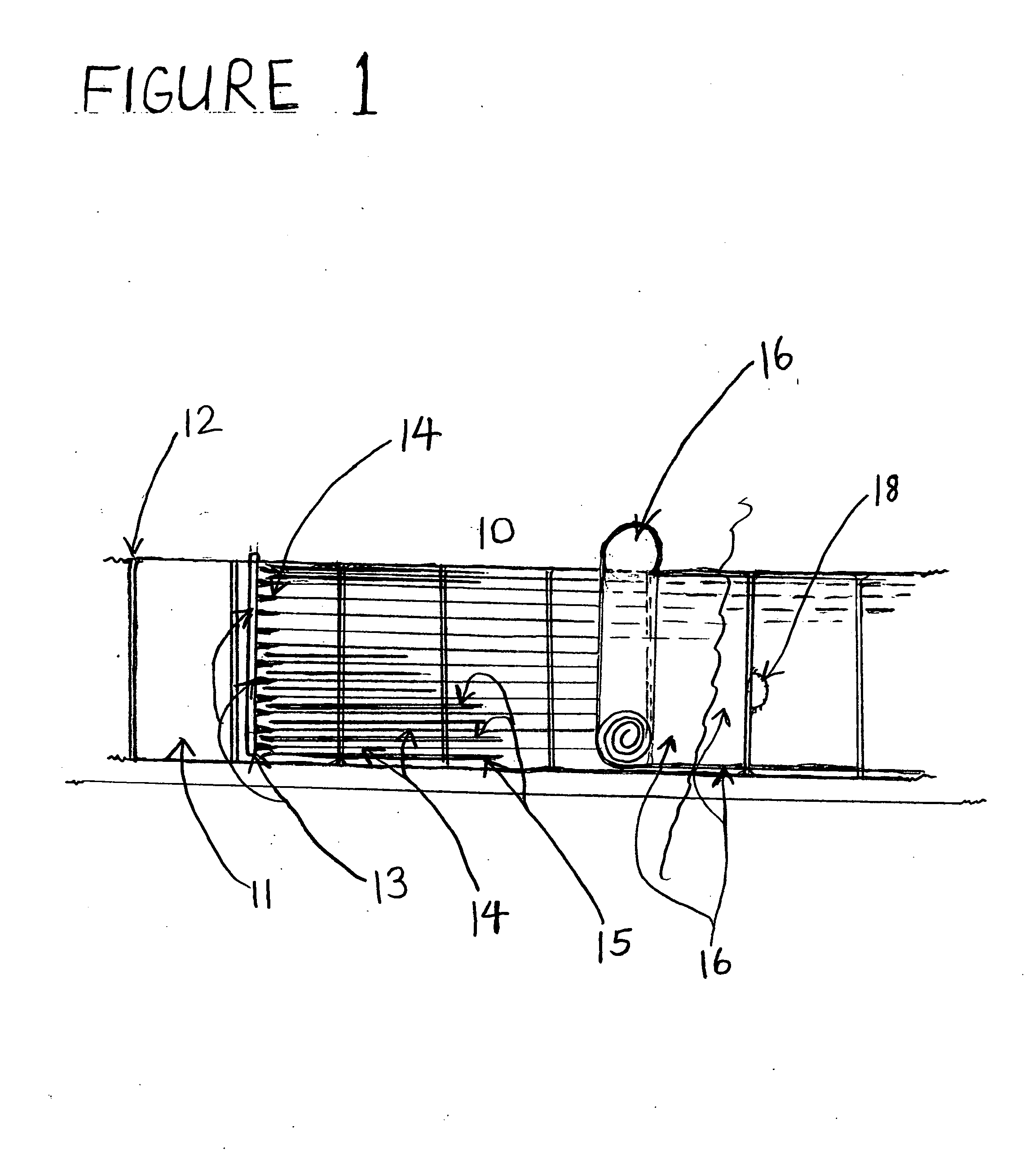
[0014]Shown in FIG. 1. is an overhead perspective view of a panel radiant reflective air spacer production line 10. Panels 11, such as oriented strand board (OSB) or plywood, move down the production line 10 with the panel's butted longwise edge to edge 12. An adhesive mixture, usually made up of ground wood, usually with various binder resins and some other materials is die or spray head applied 13 and are adhered by the adhesiveness of the composition adhesive mixture to the moving panels 11 in parallel spaced apart adhesive mixture, to be formed, air spacer lines 14. Forming guides 15 are usually used to help support and shape the mixture lines 14. As the mixture line air spacers harden radiant reflective material / film 16 adhered to the top edges of the mixture lines. When the air spacer mixture lines further hardens the panels, along with the parallel column line air spacers 17 and the radiant reflective material 16, are separated by a cutting device 18.

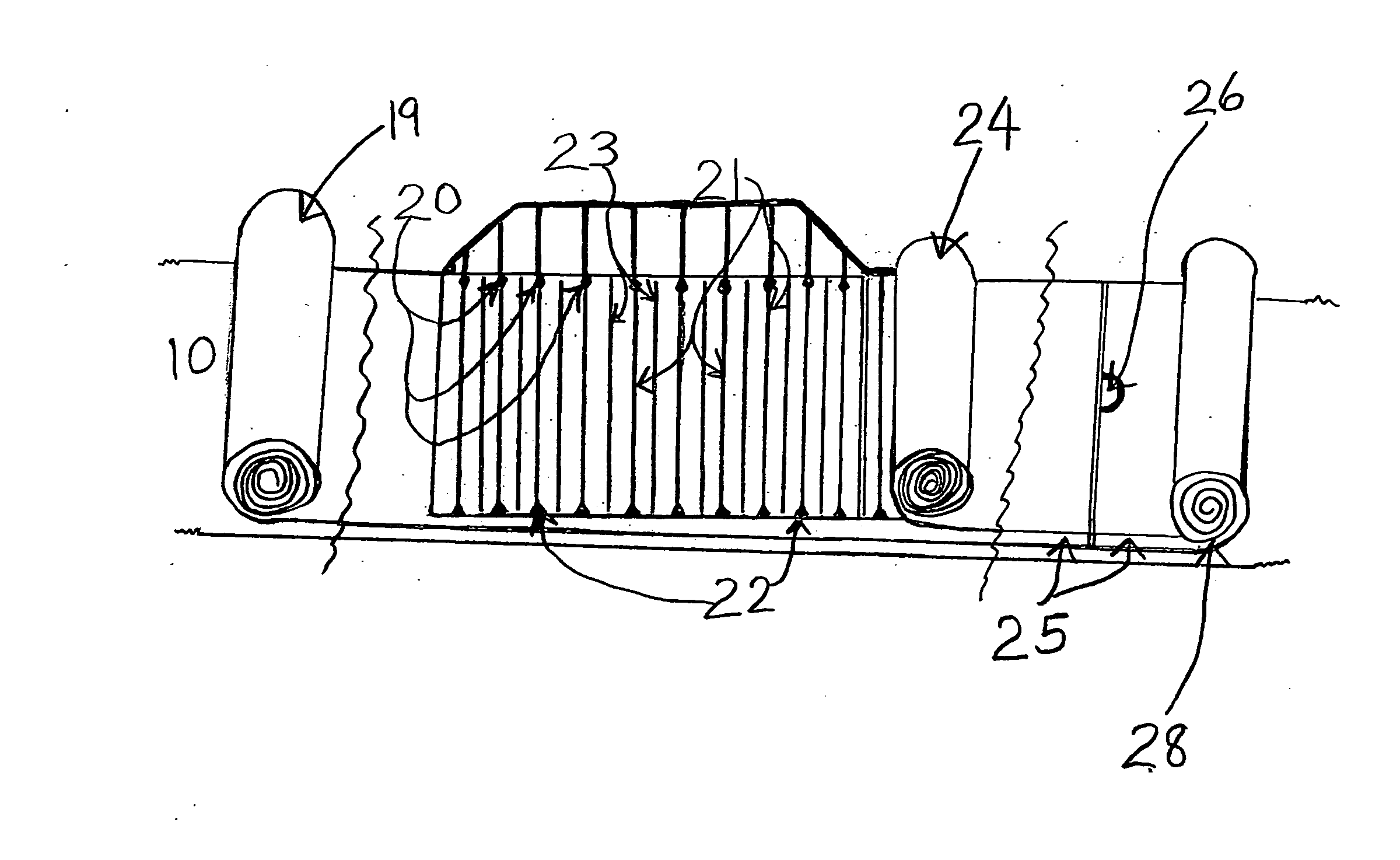
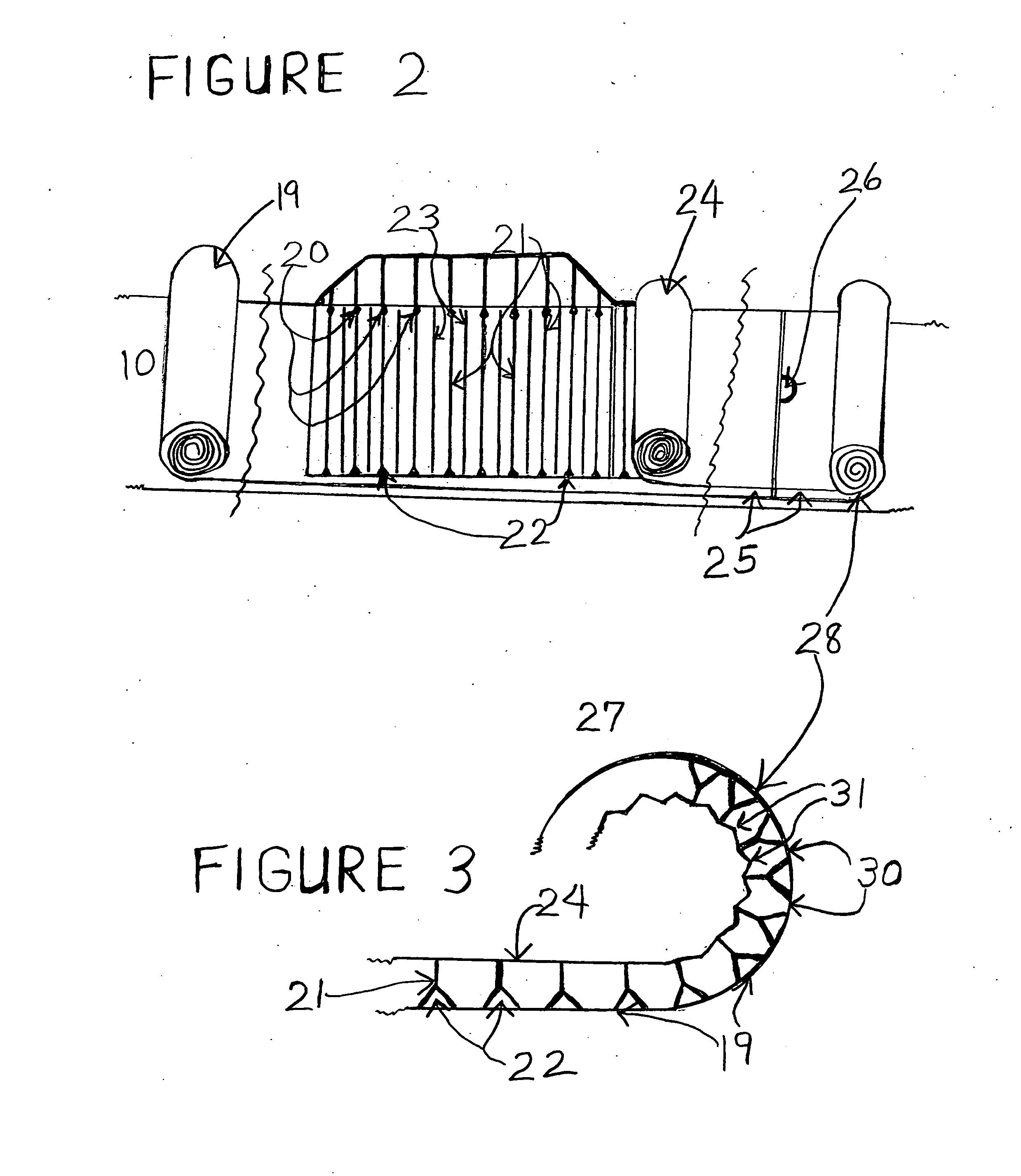
[0015]FIG. 2. in an overh...


PUM

PropertyMeasurementUnit
adhesivenessaaaaaaaaaa
shapeaaaaaaaaaa
stiffnessaaaaaaaaaa

Abstract

The invention entails the method and process to manufacture air spacers in a radiant reflective insulating, air and moisture vapor venting assembly. An adhesive mixture usually made up of ground wood, various types of binder resins such as formaldehyde based resins, and possibly other materials. The adhesive mixture is applied on various protective layers such as panels, which might be oriented strand board (OSB), plywood or even metal panels, or may be applied to more flexible protective layers such as synthetic style underlayment rolled material. The adhesive mixture is applied on the protective layer as parallel spaced lines approximately 1¼ to 1⅜th inches apart, about ⅝ to 1 inch high and 1/16 to ⅛th inch wide. Forming guides may be used to help form the adhesive mixture air spacer lines. Radiant reflective material is then adhered to the top edges of the mixture lines.

Description

CROSS-REFERENCE TO RELATED APPLICATIONS [0001]This application has cross-reference to U.S. C.I.P patent application No.: U.S. Ser. No. 13 / 507,797, filed on Jul. 30, 2012.BACKGROUND OF THE INVENTION[0002]Radiant venting and venting assemblies are comprised of protective, sometimes fairly rigid, protective upper layer, a non-collapsing columns or air spacers adhered to the underneath of the protective layer and the other ends of the air spacers adhered usually to radiant reflective material or film. The upper protective layer is held separated approximately ⅝ths to 1 inch from the radiant reflective layer by the attached air spacers, creating the needed air space for effective radiant heat reflection. When the radiant reflective insulating assembly is used under roofing or exterior wall coverings, such as sidings, brick or stucco, the upper protective layer may be rigid enough to perform as roof or wall sheathing with the air spacers being strong and stiff enough to resist collapsing ...

Claims


Application Information

Patent Timeline
Patent Type & Authority Applications(United States)
IPC IPC(8): B32B38/00
CPCB32B37/14B32B2607/00B32B2419/06B32B2309/10B32B37/1292B32B38/0004Y10T156/1084E04D13/17E04D12/00E04B1/7069E04D13/1618E04B2001/7691E04B1/78E04D12/002E04D13/16
Inventor MCCARY, JOHN, MILNER
Owner MCCARY JOHN MILNER
Why Eureka
Try Eureka