DC-DC converter

a converter and dc-dc technology, applied in the direction of dc-dc conversion, power conversion systems, instruments, etc., can solve the problems of not increasing electric power consumption on a grand scale, increasing electric power consumption by some degree, and causing the output voltage to be greatly decreased, so as to avoid the effect of greatly reducing the output voltag

Active Publication Date: 2012-06-05
MITSUMI ELECTRIC CO LTD
View PDF15 Cites 6 Cited by
  • Summary
  • Abstract
  • Description
  • Claims
  • Application Information

AI Technical Summary

Benefits of technology

[0010]The present invention was made in view of the above described problems, and it is therefore, a main object of the present invention is to provide a control technique to avoid the output voltage from being greatly decreased at the occasion of the switching from the PFM control to the PWM control, in the DC-DC converter comprising the PWM control mode and the PFM control mode so as to generate the drive pulse by the PFM control mode when the load is light.

Problems solved by technology

Further, a case may occur in which when the fluctuation width of the load is very large, the output current is to be too much even when driven by the pulse having the minimum pulse width.
When the display section is opened from this state, the electric power consumption is increased by some degree due to the lighting of the display section, and the like.
However, the electric power consumption is not increased on a grand scale suddenly.
Still, the electric power consumption may likely be increased when the subsequent operations are to be performed.

Method used


Image

  • DC-DC converter
  • DC-DC converter
  • DC-DC converter

Examples


Embodiment Construction

[0031]In the following, an embodiment of the present invention will be explained with reference to the drawings.

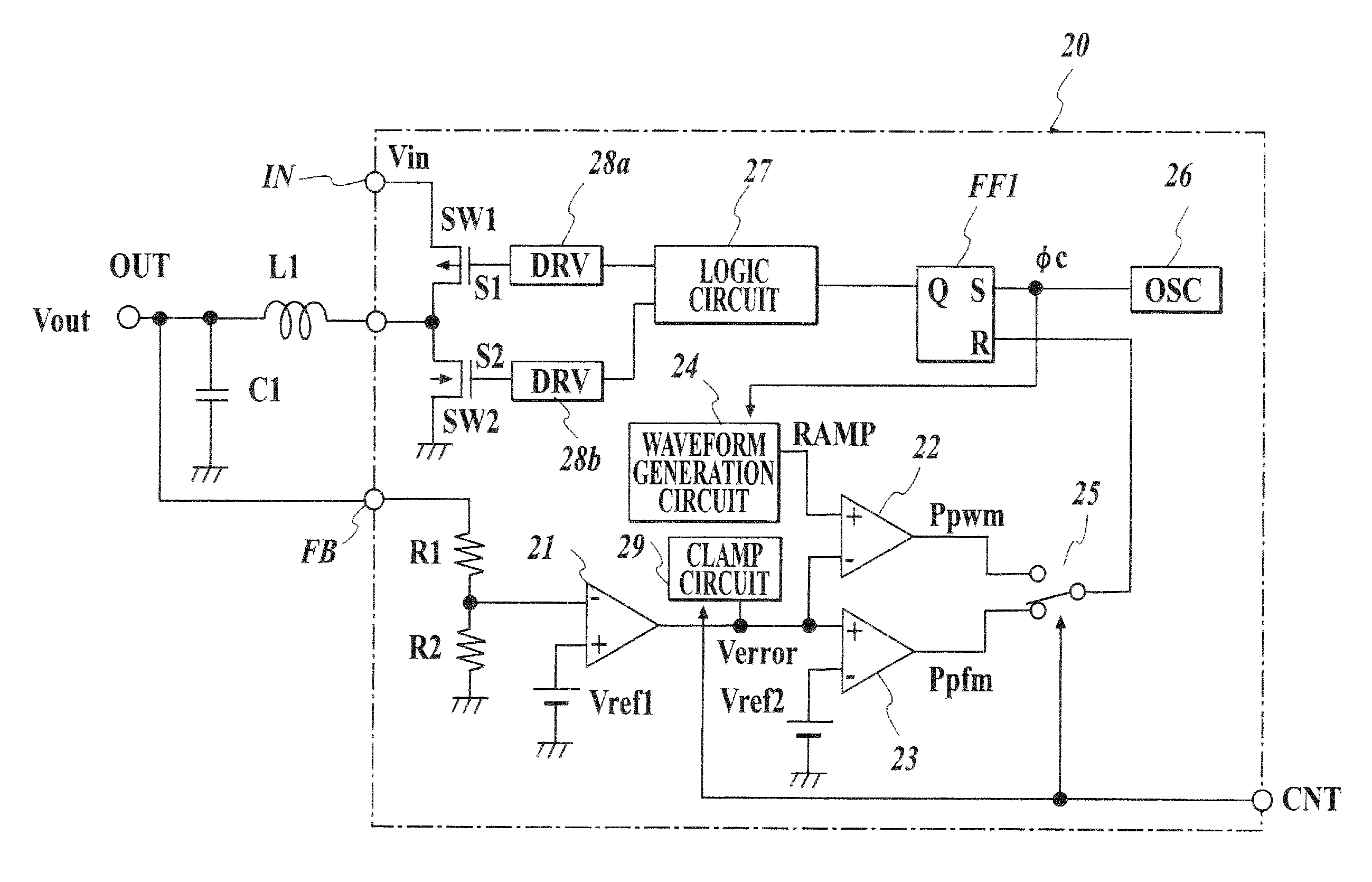
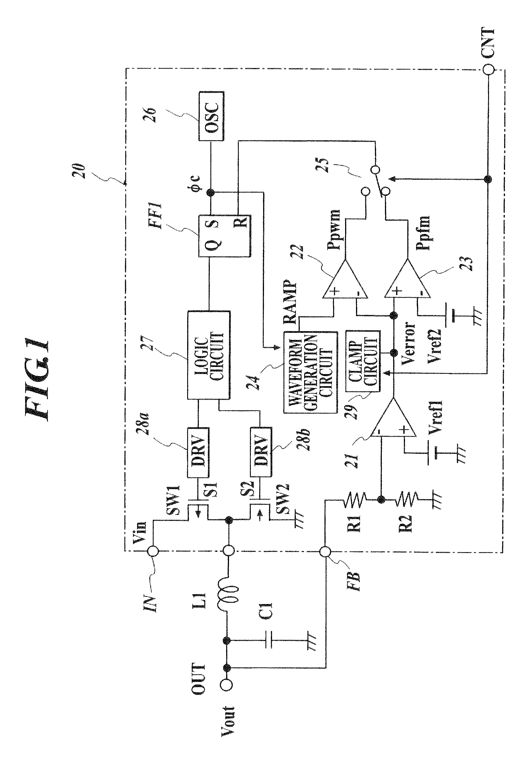
[0032]FIG. 1 shows an embodiment of the DC-DC converter of the switching regulator system to which the present invention is applied.

[0033]The DC-DC converter according to the embodiment comprises: a coil L1 as an inductor; a drive transistor SW1 as a switching element comprising a P channel metal oxide semiconductor field effect transistor (MOSFET) to flow a current to the coil L1, which is connected in between a voltage input terminal IN to be applied with the direct-current input voltage Vin, and one terminal of the coil L1; a rectification transistor SW2 comprising an N channel MOSFET; a switching control circuit 20 to control the on and off of the switching transistors SW1, SW2; and a smoothing condenser C1 which is connected in between the other terminal of the coil L1 and a ground point.

[0034]Although not specifically limited, the elements which configure the DC-DC c...


PUM


Abstract

Provided is a DC-DC converter comprising: a drive switching element so that a current flows to an inductor, the drive switching element being driven by a PWM control pulse or a PFM control pulse, wherein a direct-current input voltage supplied from a direct-current power source is converted so as to output the converted direct-current voltage having a different potential, and wherein a PWM control is performed when a load is larger than a predetermined value and a PFM control is performed when the load is smaller than the predetermined value, the DC-DC converter further comprising: a pulse width regulation section to regulate the PWM control pulse so as not to have a pulse width smaller than a predetermined pulse width, at least when the PFM control is switched to the PWM control.

Description

BACKGROUND OF THE INVENTION[0001]1. Field of the Invention[0002]The present invention relates to a DC-DC converter of a switching regulator system to convert a direct-current voltage, and for example, to a technique which is effective for being applied to a DC-DC converter comprising a pulse-width modulation (PWM) control mode and a pulse-frequency modulation (PFM) control mode, to perform a PFM drive when a current flowing in a load becomes small in amount[0003]2. Description of Related Art[0004]There is a DC-DC converter of a switching regulator system as a circuit to convert an input direct-current voltage so as to output a direct-current voltage having a different potential. As such a DC-DC converter, there is a DC-DC converter comprising a drive switching element to apply a direct-current voltage supplied from a direct-current power source such as a battery, and the like, to an inductor (a coil) and to flow the input current so that an energy is accumulated in the coil; a recti...

Claims


Application Information

Patent Timeline
Patent Type & Authority Patents(United States)
IPC IPC(8): G05F1/40
CPCH02M3/158H02M3/156H02M3/155
Inventor KUMAGAI, KEIZOHIROSHIMA, TAKASHI
Owner MITSUMI ELECTRIC CO LTD
Why Eureka
Try Eureka