Linearization of a transmit amplifier

a technology of linearization and transmit amplifier, applied in the field of data communication, can solve problems such as increased noise, affecting key transmitter parameters, and reducing isolation

Active Publication Date: 2012-06-05
TEXAS INSTR INC
View PDF11 Cites 101 Cited by
  • Summary
  • Abstract
  • Description
  • Claims
  • Application Information

AI Technical Summary

Benefits of technology

[0017]An advantage of the mechanism of the present invention is that it operates in a pseudo-closed-loop manner. It is operative to calculate the predistortion curves during the PA power ramp wherein the updated table is used during the entire burst. Alternatively, the mechanism of the present invention may also make use of samples of the output signal that are obtained during the data payload, since the instantaneous modulation (both phase and amplitude) are known to the transmitter and deviations from it caused by the AM / AM and AM / PM distortions may be determined through simple calculations. Since the existing on-chip RX resources are used for the evaluation of the distorted RF signal, no extra analog hardware is required. The resulting predistortion LUT is relatively small and the calculation is performed digitally, thus minimizing hardware requirements. Further, since the calculation may be performed on a well-behaved unmodulated signal during PA power ramp and remains constant, there is little sensitivity to an external interferer.

Problems solved by technology

The varying amplitude of these modern transmission standards cause both amplitude (AM / AM) and phase (AM / PM) domain distortions which can potentially impact key transmitter parameters such as the signal constellation and the close-in modulation spectral mask.
The distortions also cause spectral re-growth which results in reduced isolation with adjacent channels, i.e. adjacent channel power ratio (ACPR), adjacent channel leakage ratio (ACLR), etc. as well as causing increased noise due to system non-linearity.
Due to the large envelope fluctuations that are possible, such modulation schemes place additional linearity constraints on the transmitter devices.
Transmitting modulated signals with high peak to average power ratio (PAR) through nonlinear devices causes undesired spectral re-growth and increases the resulting bit error rate (BER).
In addition, the nonlinear characteristics of such devices are known to vary significantly within the span of their lifetime due to temperature and voltage changes or aging of the device itself.
For RF power amplifiers, any amplitude, phase and time distortions can have a detrimental effect on the TX system performance.
Such characterization, however, is very time and resource consuming and is not sufficiently robust.
In addition, the factory calibration time is quite long and expensive due to the need for a dedicated test bench, external test equipment and test time.
Furthermore, this scheme typically requires, for example, extensive temperature characterization for possible compensation during regular operation.
This creates the dilemma that the on-chip temperature measurements may not be accurate and may not be representative of the PA operating temperature.
Moreover, this scheme offers no reprieve from the voltage standing wave ratio (VSWR) variations due to impedance mismatch variations between the PA output and the antenna typically caused by variations in the antenna surroundings.
One prior art closed loop predistortion method has the disadvantage of requiring sophisticated and very well balanced analog circuitry for wide bandwidth loops of orthogonal phase modulation (PM) and amplitude modulation (AM) paths.
Not only does this scheme consume relatively large amounts of power, but it also is subject to failure in face of large interferers that appear at the antenna port.
Furthermore, the precise analog delay and gain balancing required takes its toll on the overall yield that can be achieved by the scheme.
Unfortunately, both of the prior art linearization techniques referred to above (i.e. both open and closed loop) are not suitable for use with the low cost GSM / EDGE / 3G cellular market targeted by the DRP™ based fully integrated cellular radios.
These prior art linearization techniques necessitate the use of expensive test equipment and typically result in a disproportionate amount of test time for linearization in contrast to other transmitter tests.
Further, these prior art approaches to linearization are not amenable to (1) ultra low cost factory testing using Very Low Cost Tester (VLCT) equipment which typically has limited RF stimulus and capture capabilities or to (2) taking advantage of built-in self test (BIST) techniques used for self calibration and automated (device and mode) failure testing.

Method used


Image

  • Linearization of a transmit amplifier
  • Linearization of a transmit amplifier
  • Linearization of a transmit amplifier

Examples


first embodiment

[0085]A block diagram illustrating the linearization mechanism of the present invention implemented in a DRP based GSM / EDGE polar transmitter is shown in FIG. 9. The example polar transmitter, generally referenced 190, comprises a transceiver circuit 200, front end module (FEM) 250, SAW filter 270, antenna 194, switcher / regulator 192, switched mode power supply (SMPS) or linear regulator 198 and battery 196. The transceiver comprises a script processor 202 (or other controller / processor device) incorporating program code means 204 for implementing the linearization mechanism of the present invention, CORDIC 228, splitter 206, multiplexers 208, 236, predistortion LUT 226, DCO 224, DPA 222, coupling capacitor 248, auxiliary low noise amplifier (LNA) / transconductance amplifier (TA) 246, low noise transconductance amplifier (LNTA) 244, switch 242, mixer 240, filters 238, 232, 212, ADC 234, gain block 230, DACs 210, 214, 216 and buffers 218, 220. 217. The FEM comprises capacitors 252, 25...

second embodiment

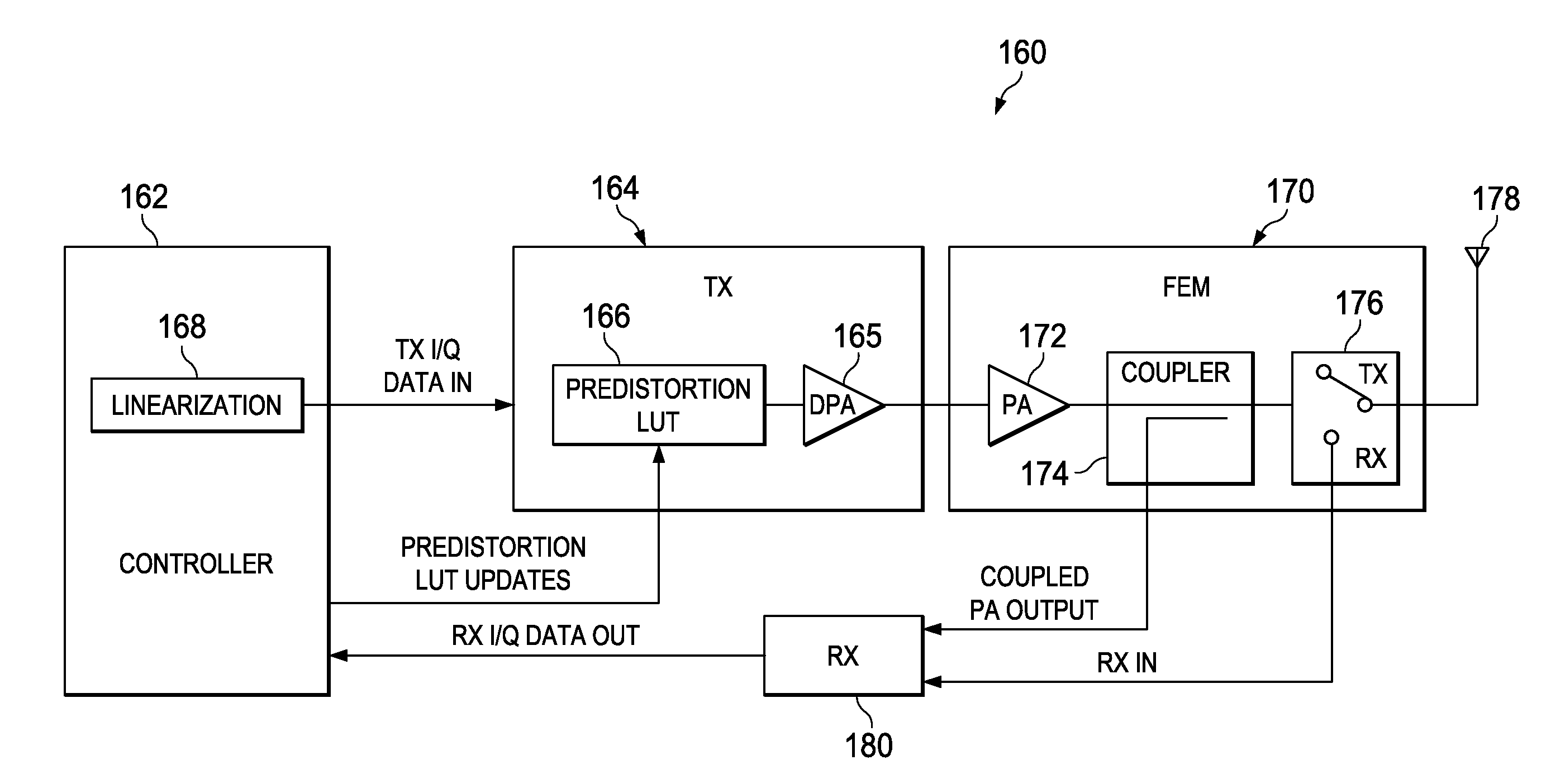
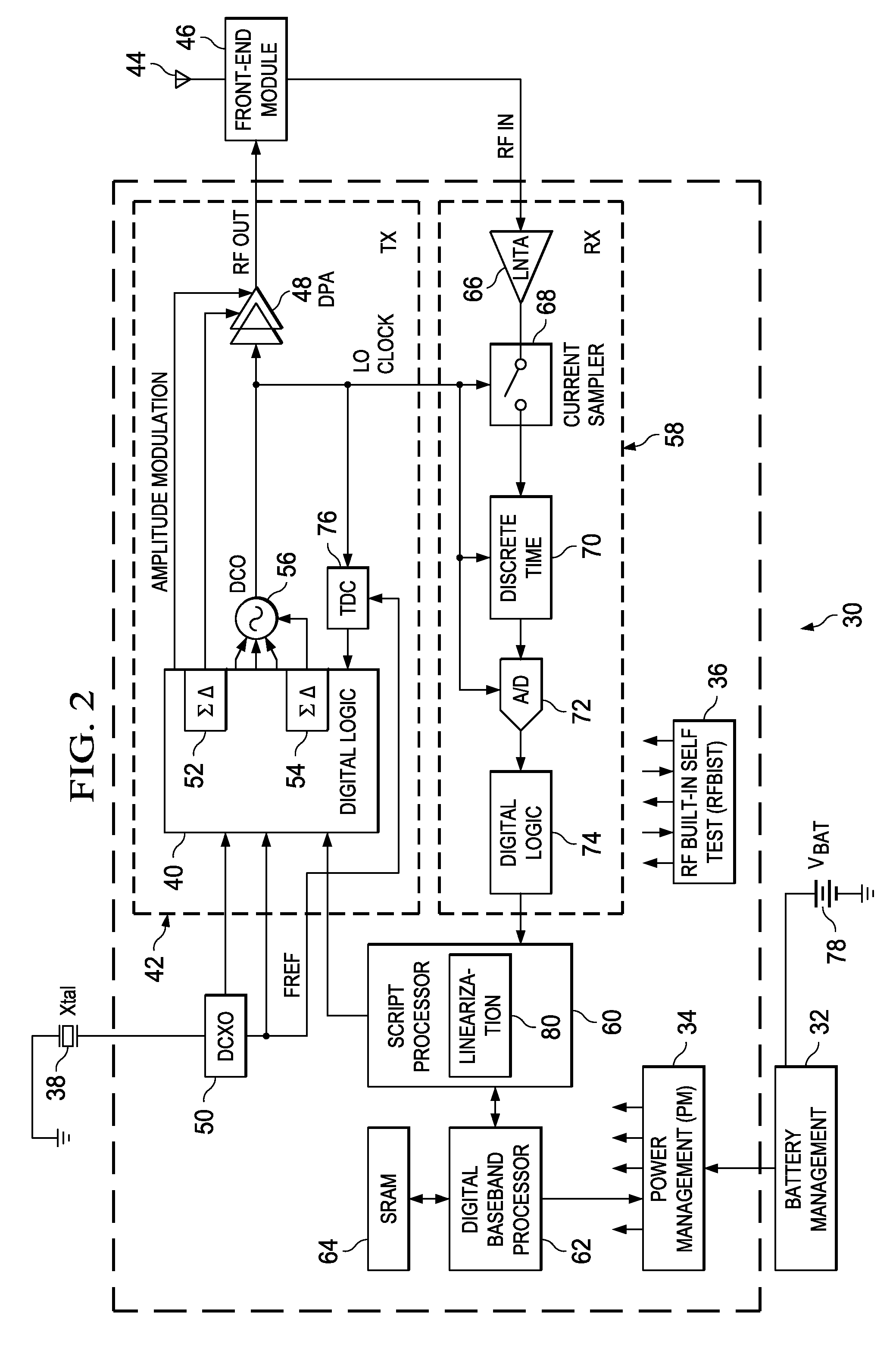
[0129]A diagram illustrating the linearization mechanism of the present invention implemented in a DRP based GSM / EDGE polar transmitter is shown in FIG. 14. The polar transmitter, generally referenced 300, comprises a transceiver circuit 302, PA module 304, SAW filter 308 and antenna 306. The transceiver comprises a script processor 318 (or other controller / processor device) incorporating program code means 316 for implementing the predistortion calibration mechanism of the present invention, pulse shaping filter 310, CORDIC and polar signal processing 312, ramp / gain normalizer 314, AM / AM and AM / PM predistortion LUT 322, AM / PM signal processing 324, local oscillator (LO) 326, DPA 328, coupling capacitor 329, auxiliary low noise amplifier (LNA) / transconductance amplifier (TA) 330, low noise transconductance amplifier (LNTA) 331, switch 332, mixer 334, filters 336, 340, multiplexer 338, ADC 339, gain block 341 and feedback CORDIC 320. The FEM comprises amplifiers 342, 344, signal coup...


PUM


Abstract

A novel apparatus and method of linearization of a digitally controlled pre-power amplifier (DPA) and RF power amplifier (PA). The mechanism is operative to perform predistortion calibration to compensate for nonlinearities in the DPA and PA circuits. A predistortion look up table (LUT) stores measured distortion compensation data that is applied to the TX data before being input to the digital to frequency converter (DFC), DPA and PA. The mechanism of the invention takes advantage of the on-chip receiver, which is normally inactive during the TX burst in a half-duplex operation, to demodulate the RF PA output and use the digital I / Q RX outputs to perform calibration of the TX pre-distortion tables. Controlled RF coupling is used to provide a sample of the RF output signal that to the receiver chain. The contents of the predistortion LUT are typically updated during the PA power up or down ramp. While the digitally-controlled PA (DPA) code is increasing (or decreasing), the amplitude and phase of the recovered I / Q samples are used to determine the instantaneous value of the AM / AM and AM / PM pre-distortion from which an update to the predistortion tables may be computed.

Description

REFERENCE TO PRIORITY APPLICATION[0001]This application claims priority to U.S. Provisional Application Ser. No. 60 / 773,775, filed Feb. 15, 2006, entitled “Linearization of an RF Power Amplifier”, incorporated herein by reference in its entirety.FIELD OF THE INVENTION[0002]The present invention relates to the field of data communications and more particularly relates to an apparatus for and method of linearization of a transmit amplifier.BACKGROUND OF THE INVENTION[0003]Modern complex envelope modulation schemes such as those used in Enhanced Data rates for GSM Evolution (EDGE), Wideband Code Division Multiple Access (WCDMA), Bluetooth-Enhanced Data Rate (BT-EDR), Wireless Local Area Network (WLAN), Worldwide Interoperability for Microwave Access (WiMAX), etc. impose strict performance requirements on transceivers developed to support them, especially wireless handset transmitters. Stringent performance requirements for many aspects of polar transmitters exist as well. A circuit dia...

Claims


Application Information

Patent Timeline
Patent Type & Authority Patents(United States)
IPC IPC(8): H04B1/04
CPCH04B1/0475H04B2001/0425H03F1/3241
Inventor WAHEED, KHURRAMSTASZEWSKI, ROBERT B.REZEQ, SAMEH S.ELIEZER, OREN E.
Owner TEXAS INSTR INC
Why Eureka
Try Eureka