Multi-mode control loop with improved performance for mass flow controller

a controller and multi-mode technology, applied in the field of mass flow controllers, can solve the problems of difficult to accurately determine the fluid flow rate and prevent, and achieve the effect of preventing the flow rate overshoot of the new setpoint value, and preventing the flow rate overshoo

Active Publication Date: 2012-06-05
HITACHI METALS LTD
View PDF15 Cites 2 Cited by
  • Summary
  • Abstract
  • Description
  • Claims
  • Application Information

AI Technical Summary

Benefits of technology

[0005]Another embodiment of the invention comprises a method of adjusting a flow rate of fluid in a mass flow controller in order to prevent flow rate overshoot. One method is comprised of receiving an original set point value and subsequently changing the set point value to a new set point value. A difference between the new set point value and a measured fluid flow rate is determined to obtain an error signal. A signal adder combines the error signal with a signal emitted from a proportional signal modifier to obtain a combination signal. The signal emitted from the proportional signal modifier is obtained after applying differentiation and a proportional modifier to a measured flow rate signal. An integral signal modifier is applied to the combination signal and outputs an integrated signal, which is received by a valve and used to adjust a valve opening accordingly. Through application of the proportional and integral signal modifiers in this manner, flow rate overshoot of the new setpoint value is prevented.
[0006]An additional embodiment type is a mass flow rate digital controller. The digital controller is adapted to receive and output electrical signals to prevent overshoot of a desired mass flow rate in an MFC. One digital controller comprises at least one input. The at least one input is adapted to receive a setpoint signal and a sensor signal. The digital controller further comprises a proportional signal modifier having a differentiation module. The proportional signal modifier with a differentiation module is adapted to receive the sensor signal and output a proportional signal. A first signal adder in the controller is adapted to receive the setpoint signal and sensor signal and output an error signal. A second adder is adapted to receive the error signal and the proportional signal and output a combination signal. The combination signal is adapted to be received by an integral signal modifier. The integral signal modifier outputs an integrated signal. The integrated signal is then output by the digital controller, received by, and used to adjust, a valve, preventing overshoot of the flow rate.

Problems solved by technology

However, it is often difficult to accurately determine the fluid flow rate and prevent overshoot for step changes in setpoint because performance of the MFC varies greatly among fluid type, fluid pressure, and setpoint value.

Method used


Image

  • Multi-mode control loop with improved performance for mass flow controller
  • Multi-mode control loop with improved performance for mass flow controller
  • Multi-mode control loop with improved performance for mass flow controller

Examples


Embodiment Construction

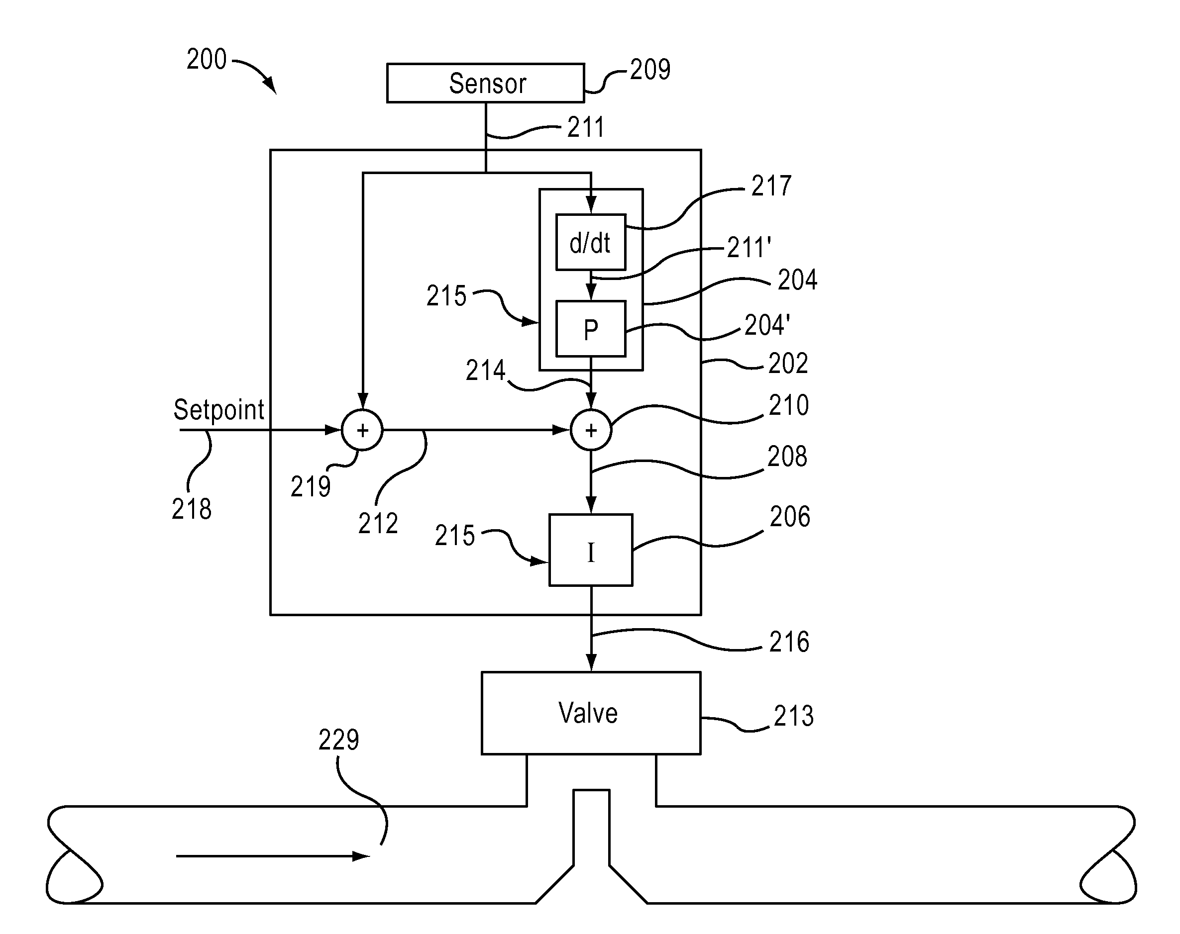
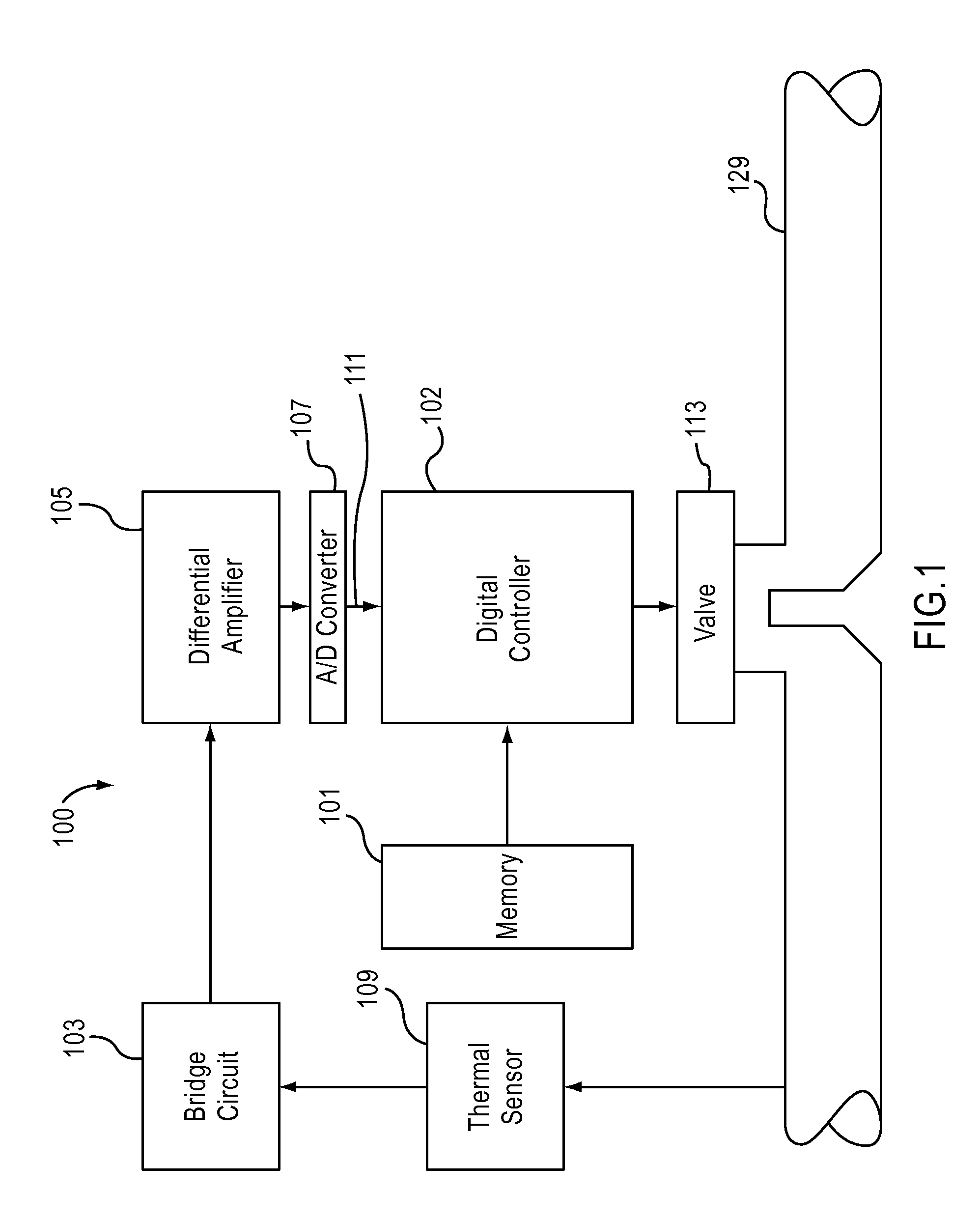
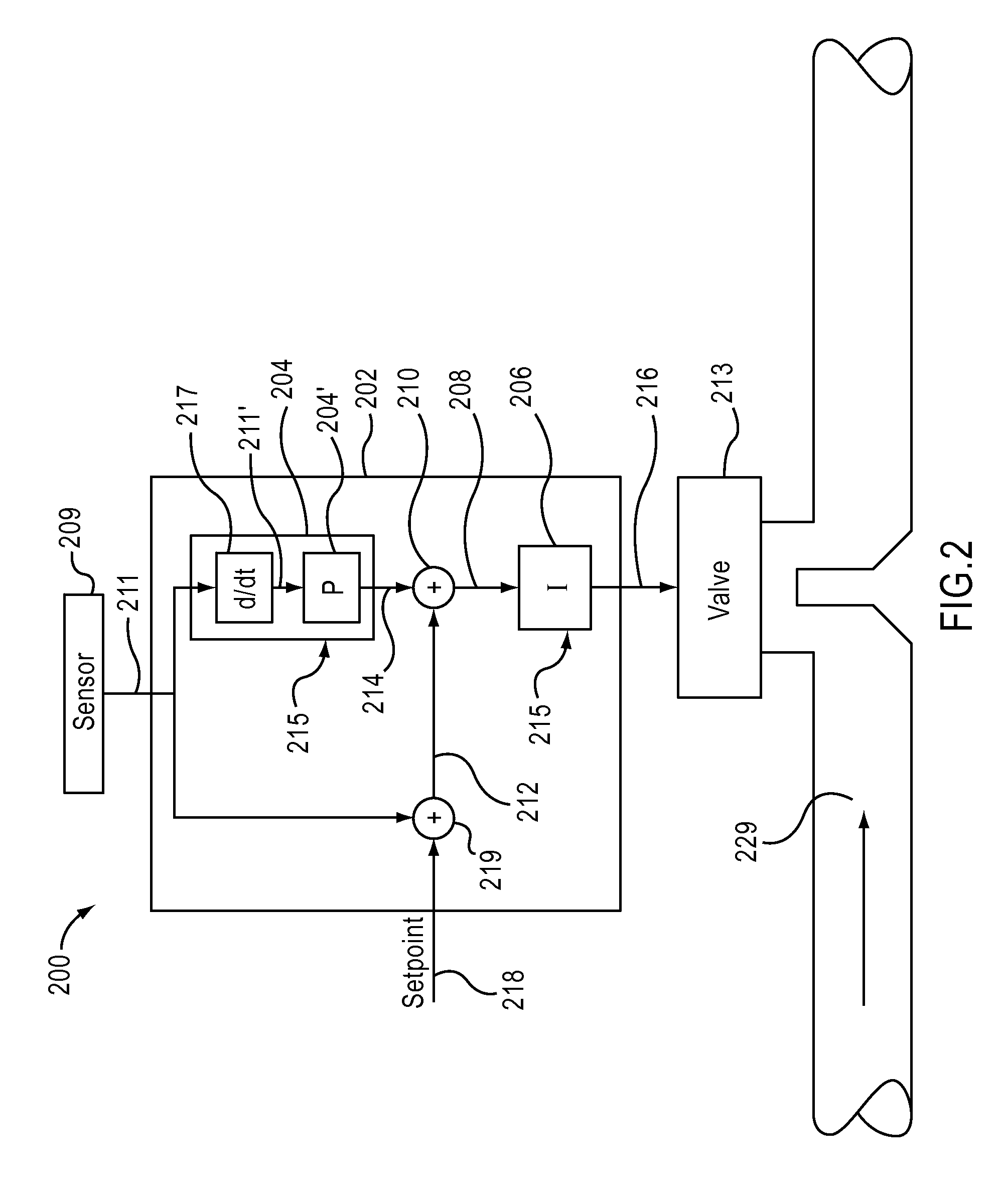
[0015]Referring now to the drawings, where like or similar elements are designated with identical reference numerals throughout the several views where appropriate, and referring in particular to FIG. 1, shown is a mass flow controller 100 adapted to substantially prevent flow rate overshoot upon a step change occurring in the setpoint. As seen in FIG. 1, included in one MFC 100 is a digital controller 102. The controller 102 may be a modified PI controller in one embodiment. Furthermore, the controller 102 may be comprised of a processing unit, e.g., a processor, adapted to receive one or more input signals and output one or more output signals, with the one or more output signals adapted to modify a control valve 113 in response to the one or more input signals. The digital controller 102 may also be referred to as a digital control system.

[0016]The MFC 100 may also be comprised of a memory device 101 that may store information for use by the controller 102. Although the memory de...


PUM


Abstract

One embodiment of the invention comprises a mass flow controller comprising a digital controller, a valve, and a sensor. The digital controller is adapted to implement a control loop having a proportional signal modifier in series with an integral signal modifier. The integral signal modifier is adapted to receive a combination signal and output an integrated signal. The valve is adapted to receive the integrated signal and adjust a valve opening in accordance with the integrated signal. The sensor is adapted to output a measured flow rate signal indicative of an actual fluid flow rate in the mass flow controller. The measured flow rate signal is received by the proportional signal modifier and used in conjunction with a setpoint signal to determine the error signal.

Description

FIELD OF THE INVENTION[0001]The present invention generally relates to a mass flow controller, or “MFC”. In particular, but not by way of limitation, the present invention relates to a control system adapted to substantially decrease flow rate overshoot in a MFC.BACKGROUND OF THE INVENTION[0002]MFCs are often used across multiple fluid types and applications. Furthermore, it is often required that the MFCs be adapted to quickly respond to changes in the desired fluid mass flow rate, or “setpoint”. For example, many applications only operate properly when, upon a step change in the setpoint, the MFC outputs an accurate mass flow rate of fluid and prevents overshoot of the new flow rate. However, it is often difficult to accurately determine the fluid flow rate and prevent overshoot for step changes in setpoint because performance of the MFC varies greatly among fluid type, fluid pressure, and setpoint value.SUMMARY OF THE INVENTION[0003]Exemplary embodiments of the present invention ...

Claims


Application Information

Patent Timeline
Patent Type & Authority Patents(United States)
IPC IPC(8): G05B13/02G05D7/00G05D11/00G05D11/02G05D11/16G05D3/12G05D5/00G05D9/00
CPCG05B11/42G05D7/0635
Inventor SMIRNOV, ALEXEI V.WESTRA, MICHAEL LYNNWIDENER, DEMITRI
Owner HITACHI METALS LTD
Why Eureka
Try Eureka