Fundamental wave beat component detecting method and measuring target signal sampling apparatus and waveform observation system using the same

a component detection and component detection technology, applied in the direction of instruments, digital computer details, spectral/fourier analysis, etc., can solve the problems of inability to accurately reproduce waveforms, phase of waveforms and magnitudes of fluctuation of amplitudes, and inability to accurately grasp phase of waveforms and magnitudes of waveform fluctuation, etc., to achieve high accuracy, high accuracy, high accuracy

Inactive Publication Date: 2012-06-05
ANRITSU CORP
View PDF10 Cites 4 Cited by
  • Summary
  • Abstract
  • Description
  • Claims
  • Application Information

AI Technical Summary

Benefits of technology

[0095]An object of the present invention is to solve these problems and provide a fundamental beat component detecting method for determining which peak signal is a beat component originating from the fundamental wave component of the measuring target signal among the plural peak signals contained in the sampling result even if the measuring target signal is a signal having plural harmonic components having a similar power, and a sampling apparatus and a waveform observation system which can execute stable acquisition and observation of the waveform information about the measuring target signal by detecting the repetition frequency of the measuring target signal accurately using the method and construct the entire system easily.
[0149]According to the fundamental wave beat component detecting method of the present invention, as described above, plural peak signals which appear in a band ½ of the sampling frequency fs are detected from a spectrum obtained by analyzing a signal obtained by sampling the measuring target signal P with a certain frequency fs so as to obtain the frequencies fb[i] (i=1, 2, 3 . . . ) of those plural peak signals, and then, each theoretical frequencies fc[i,j] (i=1, 2, 3 . . . , j=1, 2, 3 . . . ) of the beat component (harmonic beat component) originating from the harmonic component of the measuring target signal P is calculated successively when assuming that each of those plural peak signals is a beat component (fundamental wave beat component) originating from the fundamental wave of the measuring target signal P, and each theoretical frequencies fc[i,j] of these harmonic beat components is successively compared with the frequencies fb[i] of the plural peak signals and based on a result of the comparison of the peak signals in succession, the peak signal which gives the theoretical frequencies fc[k,j] (k is an integer) of the harmonic beat component which agrees with those frequencies fb[i] most is determined to be the fundamental wave beat component. Consequently, even if the measuring target signal P is a signal having plural harmonic components having a similar power, the fundamental wave beat component can be detected at a high accuracy without any error.

Problems solved by technology

However, unless sampling at the time of sampling of the measuring target signal P is started from an identical phase position of the repetition waveform of the measuring target signal P, there occurs such an inconvenience that a displayed waveform may be shifted in a time axis each time in case of the observation mode which displays the waveform of the measuring target signal with the incidental image.
In the averaging mode, the averaging processing cannot be performed accurately and consequently, the waveform cannot be reproduced accurately, and further, the phase of the waveform and a magnitude of the fluctuation of the amplitude cannot be grasped accurately.
However, depending on a case, there occurs a following problem.
Even if an approximate value of the repetition cycle of the waveform of a measuring target signal which is a target for observation or its frequency is known, no proper sampling cycle can be set for the waveform of a measuring target signal which is a target for observation if its accurate value is unknown, so that no desired waveform can be observed.
Further, this kind of the waveform observation apparatus has another problem that it needs an optical mixer for generating a narrow optical sampling pulse or mixing lights so that the entire apparatus including a display portion becomes complicated and expensive.

Method used


Image

  • Fundamental wave beat component detecting method and measuring target signal sampling apparatus and waveform observation system using the same
  • Fundamental wave beat component detecting method and measuring target signal sampling apparatus and waveform observation system using the same
  • Fundamental wave beat component detecting method and measuring target signal sampling apparatus and waveform observation system using the same

Examples


first embodiment

[0181](First Embodiment)

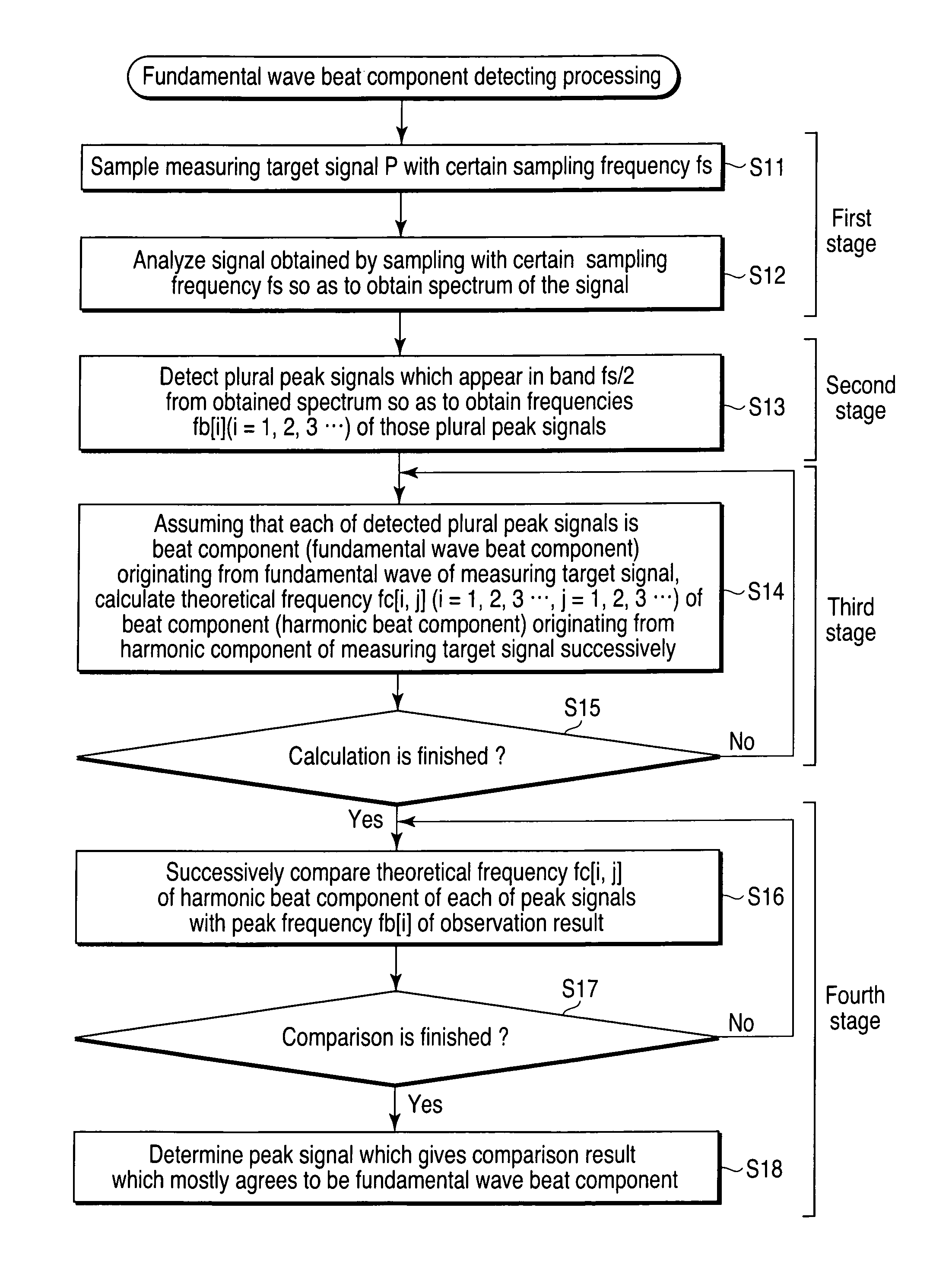
[0182]FIG. 1 is a flow chart for explaining the procedure of the fundamental wave beat component detecting method according to the first embodiment of the present invention.

[0183]A fundamental wave beat component detecting method according to the present invention basically includes: a first stage of analyzing a signal obtained by sampling a measuring target signal P with a sampling frequency fs so as to obtain a spectrum thereof; a second stage of detecting plural peak signals which appear in a band ½ of the sampling frequency fs from the spectrum obtained in the first stage so as to obtain the frequencies fb[i] (i=1, 2, 3 . . . ) of the plural peak signals; a third stage of assuming that each of the plural peak signals detected in the second stage is a beat component (fundamental wave beat component) originating from the fundamental wave of the measuring target signal P so as to calculate each theoretical frequency fc[i,j] (i=1, 2, 3 . . . , j=1, 2, 3 . . ....

second embodiment

[0216](Second Embodiment)

[0217]FIG. 4 is a block diagram for explaining the structure of the waveform observation system containing the sampling apparatus for the measuring target signal according to the second embodiment of the present invention.

[0218]More specifically, as shown in FIG. 4, the waveform observation system 20 of the second embodiment includes the parameter specifying portion 22, the arithmetic operation portion 23, the signal generating portion 24, the sampling pulse generating portion 25, the optical sampling portion 26 and the repetition frequency calculating portion 28, to execute step S11 of the fundamental wave beat component detecting method according to the first embodiment as described above like the waveform observation system 20 containing the sampling apparatus for the measuring target signal according to an earlier application of this inventor shown in FIG. 15.

[0219]More specifically, as shown in FIG. 4, the waveform observation system 20 of the second em...

third embodiment

[0273](Third Embodiment)

[0274]FIG. 9 is a block diagram for explaining the configuration of the waveform observation system according to the third embodiment of the present invention.

[0275]The waveform observation system 40 of the third embodiment is configured so that the functions of the sampling apparatus 21 constituting the waveform observation system 20 of the second embodiment and the digital oscilloscope 60 are accommodated and integrated in a common casing.

[0276]More specifically, the waveform observation system 40 of this third embodiment includes an A / D converter 43, a data acquisition control portion 44, a waveform data memory 45, a display control portion 46, a display portion 47 and an observation mode specifying portion 48 as well as the respective components of the sampling apparatus 21 of FIG. 4 according to the second embodiment.

[0277]The A / D converter 43 carries out A / D conversion processing for a pulse signal Eo output from the optical sampling portion 26 each tim...


PUM


Abstract

Frequencies of plural peak signals which appear in a band ½ of a sampling frequency are detected from a spectrum obtained from a measuring target signal sampled with the sampling frequency in order to detect the repetition frequency of the measuring target signal having plural harmonic components with a similar power. Each of the plural peak signals is successively assumed to be a fundamental wave beat component originating from the fundamental wave of the measuring target signal and theoretical frequencies of harmonic beat components originating from harmonic components of the measuring target signal are successively calculated. The theoretical frequencies are compared with the frequencies of the plural peak signals to determine one of the plural peak signals as a fundamental wave beat component originating from the fundamental wave of the measuring target signal.

Description

[0001]This application is a U.S. National Phase Application under 35 USC 371 of International Application PCT / JP2008 / 056809 filed Apr. 4, 2008.TECHNICAL FIELD[0002]The present invention relates to a fundamental wave beat component detecting method, and a measuring target signal sampling apparatus and a waveform observation system using the same, and more particularly to a fundamental wave beat component detecting method in which even if a measuring target signal is a signal having a plurality of harmonic components having a similar power in a system which samples an optical signal modulated by fast repetition signals so as to acquire and observe its waveform information, the repetition frequency of the measuring target signal can be detected accurately to achieve stable waveform information acquisition and observation, a measuring target signal sampling apparatus and a waveform observation system using the same.BACKGROUND ART[0003]For example, a waveform observation apparatus 10 sho...

Claims


Application Information

Patent Timeline
Patent Type & Authority Patents(United States)
IPC IPC(8): G01R23/16G10L19/14G01R23/00H04B15/00
CPCG01R23/20G01R19/2509G01R23/14G01R13/0272
Inventor TSUDA, YUKIO
Owner ANRITSU CORP
Why Eureka
Try Eureka