Latching device for a spring-type drive

a latching device and spring-type technology, applied in the direction of carpet fasteners, contact mechanisms, snap-action arrangements, etc., can solve the problems of enlargement of the overall latching device, increased material and space requirements, and increased friction during a movement of the supporting elements in the slot track, so as to simplify the mounting of the latching device, reduce the necessary forces required to move the individual movable elements, and reduce friction

Inactive Publication Date: 2012-06-12
SIEMENS AG
View PDF15 Cites 3 Cited by
  • Summary
  • Abstract
  • Description
  • Claims
  • Application Information

AI Technical Summary

Benefits of technology

[0012]The advantages that can be achieved with the invention consist in particular in the fact that, with a small triggering stroke, a small triggering force and with a low mass of the moving parts, a greater stroke of the compression element is made possible. This arrangement additionally permits a rapid response upon the occurrence of a triggering command for a spring-type drive. Furthermore, the expenditure on materials and fabrication, as compared with existing solutions, is lower. For instance, the stop can be formed in such a way that a recess is provided in the first guide in the region of the first guide located immediately under the direction of operation of the compression element, so that the lower supporting element can be deflected in the operating direction and is held stably there in a recess acting appropriately as a stop. However, the stop can also be located in an alternative position.
[0029]A variation in the stroke of the compression element can likewise be effected advantageously by it being possible to vary the length of the displacement travel of at least one supporting element.

Problems solved by technology

However, in the case of this triggering principle, the result is that the stroke of the compression element can only be as great as the magnitude of the diameters of the two inner rollers.
In the event of a desired enlargement of the stroke of the compression element, the diameters of at least the inner rollers would consequently have to be enlarged, which likewise would result in an enlargement of the overall latching device and therefore entails an increased requirement for materials and space.

Method used


Image

  • Latching device for a spring-type drive
  • Latching device for a spring-type drive

Examples


Embodiment Construction

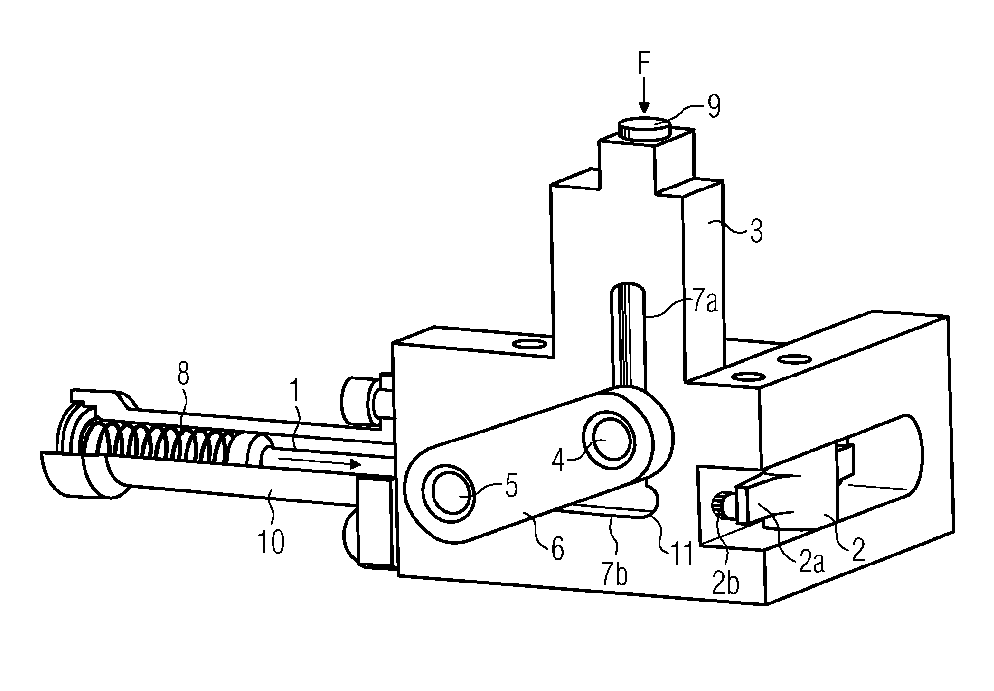
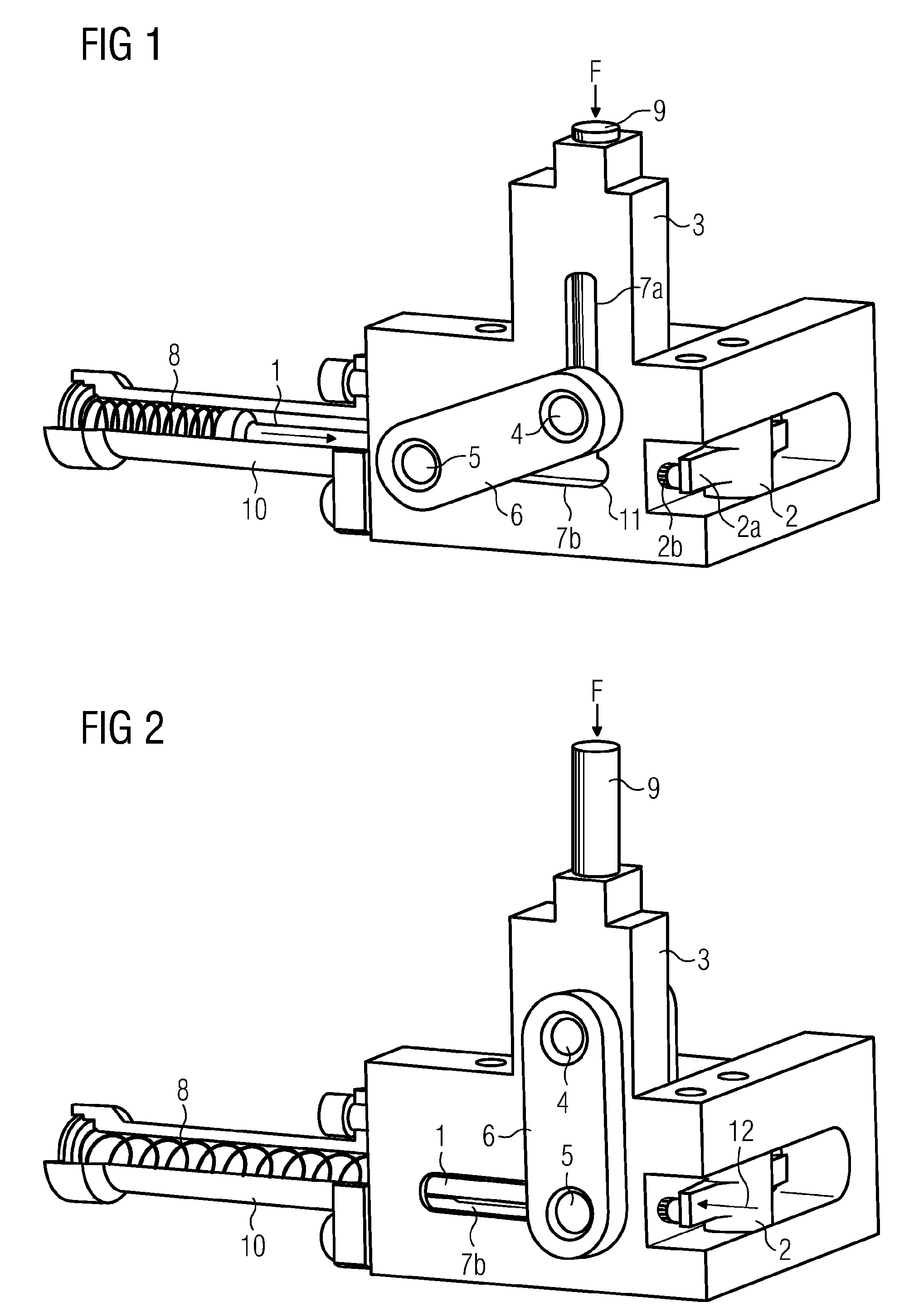
[0034]By using the latching device illustrated in the triggered state in FIG. 1, its fundamental structure will be described first. The latching device has a housing 3, which serves as a chassis to accommodate further fittings. The housing 3 is, for example, a metallic casting or milled part. Arranged on the housing 3 is a resetting device 1, which is arranged in the interior of a sleeve 10 such that it can be displaced along the sleeve 10. On the side of the housing 3 facing away from the sleeve 10 there is arranged a triggering device 2. The triggering device 2 has a cam 2a. The triggering device 2 is mounted such that it can rotate, so that the cam 2a can effect a translational movement of a disengaging pin 2b in the event of a rotational movement of the triggering device 2. The disengaging pin 2b can be moved back and forth substantially in the same direction as the resetting device 1.

[0035]Furthermore, the housing 3 has a first and a second guide 7a, 7b. The guides 7a, 7b are i...


PUM


Abstract

A latching device has a resetting device, a triggering device for producing a triggering force which acts in a first direction, a compression element, and an upper and a lower supporting element which, in the latched state, are arranged one above the other in a housing and are connected to each other by at least one coupler such that they are at a distance from each other, and which, in the latched state, are acted upon, to provide a spring-type drive, by a compressive force applied along a line of action via the compression element. The lower supporting element, loaded by the compressive force in the latched state, is deflected against a stop and is held in that position. The paths of movement of the upper and of the lower supporting element are defined by the housing by way of guides. The path of movement for the lower supporting element runs substantially perpendicular to the path of movement of the upper supporting element.

Description

BACKGROUND OF THE INVENTION[0001]1. Field of the Invention[0002]The invention relates to a latching device having a resetting device, having a triggering device, having a compression element and having supporting elements which are arranged one above the other in a housing and which, in the latched state, are acted upon with a compressive force applied via a compression element, to provide a spring-type drive.[0003]2. PRIOR ART[0004]Latching devices of this type for spring-type drives are employed, for example, in high-voltage circuit breakers. The storage spring contained in a spring-type drive can be kept in a stressed state by a latching device. By means of a latching device, a comparatively large amount of stored energy can be released from the stressed storage spring in a controlled manner. In order to release the stored energy, the latching device has a triggering device, which operates with an amount of energy that is small as compared with the energy to be released.[0005]It ...

Claims


Application Information

Patent Timeline
Patent Type & Authority Patents(United States)
IPC IPC(8): E05C1/06E05C19/00
CPCH01H3/3031Y10S292/37Y10S292/61Y10T292/03Y10T292/0972Y10T292/1016
Inventor LUTZKE, GUNNAR
Owner SIEMENS AG
Why Eureka
Try Eureka