Method for manufacturing planar heating element using carbon micro-fibers

a technology of carbon microfibers and heating elements, applied in the direction of coatings, other domestic articles, bands, etc., can solve the problems of limited heating temperature limited material of insulating films, and limited temperature and use of conventional planar heating elements. achieve the effect of reducing energy consumption, improving temperature application range, and efficiently reducing energy consumption

Inactive Publication Date: 2012-06-12
NAOS
View PDF9 Cites 12 Cited by
  • Summary
  • Abstract
  • Description
  • Claims
  • Application Information

AI Technical Summary

Benefits of technology

[0040]According to a method for manufacturing a planar heating element using carbon micro-fibers of the present invention, a carbon heating element having a complex structure is used to highly improve a temperature application range, thereby allowing the heating element to be used at a high temperature and applied to various uses. Further, an insulating finishing material is selectively used according to the heating temperature to form an insulating layer, thereby manufacturing heating elements of various temperatures.
[0041]Further, according to a method for manufacturing a planar heating element using carbon micro-fibers of the present invention, compared to a conventional planar heating element, it is possible to reduce energy consumption up to a maximum of 75% by configuring and designing the heating element capable of efficiently reducing an energy consumption amount by removing an unnecessary space from the planar heating element. Further, it is possible to form the planar heating element capable of providing health promotion by using environment-friendly materials such as carbon, which emit a large amount of far infrared rays.
[0042]Further, according to a method for manufacturing a planar heating element using carbon micro-fibers of the present invention, an insulating layer is formed by using a T-die ejecting molding method instead of a conventional heating element or heat roller pressing laminating method or by heat-pressing molding, and particles of the carbon micro-fibers are mixed with an organic binder. Accordingly, it is possible to relatively prolong a life of the heating element by preventing the carbon micro-fibers from being in contact with air. Further, an insulating material is selected from a group consisting of PE, LDPE, LLDPE, PVC, tarpaulin, TPU, PU (polyurethane) and the like, which have ductility even in folding, and resin films such as epoxy impregnated fiberglass cloth (prepreg) and phenolic impregnated fiberglass cloth, which have high hardness to provide a mechanical strength to the insulating material. Accordingly, it is possible to form heating elements having various functions for various uses.
[0043]Further, according to a method for manufacturing a planar heating element using carbon micro-fibers of the present invention, it is possible to completely replace a conventional heating element using resistance heat of a nichrome wire by efficiently coating carbon micro-fibers, carbon nanotubes and carbon powder. Further, it is possible to form a single heating element having a large width and an ultra thin heating element without temperature restriction by overcoming drawbacks of a carbon powder printed heating element serving as an initial module of the planar heating element. Thus, it is possible to form various convenient heating elements or heating modules using DC and AC electricity without restriction by solving problems in installation and use, for example, space restriction, thereby various convenient heating elements.
[0044]Further, according to a method for manufacturing a planar heating element using carbon micro-fibers of the present invention, the planar heating element has a structure without the bad effect of an electromagnetic wave generated in a conventional planar heating element, thereby having advantages in health. Further, it is possible to highly reduce an electricity consumption amount compared to other planar heating elements, thereby increasing economical efficiency and minimizing environmental pollution.

Problems solved by technology

However, the conventional planar heating element has a limited heating temperature.
Theoretically, when a distance between both electrodes is 300˜500 mm, a heating temperature is about 83° C. Actually, the temperature and use of the conventional planar heating element are restricted and a material of an insulating film is limited.
In the heating elements of a specified temperature (about 65° C.) or more, EVA of the insulating film swells, thereby causing defects on the appearance and performance of the planar heating element.
Further, the conventional planar heating element is sensitive to folding.
An electric shock and defects may occur due to wrinkling in use.
However, it is difficult to find an adhesive insulating material and a manufacturing method while maintaining a regularly arranged pattern.

Method used


Image

  • Method for manufacturing planar heating element using carbon micro-fibers
  • Method for manufacturing planar heating element using carbon micro-fibers
  • Method for manufacturing planar heating element using carbon micro-fibers

Examples


first embodiment

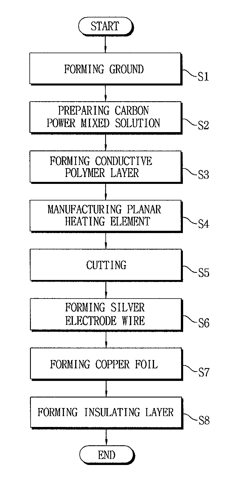
[0063]Hereinafter, a method for manufacturing a planar heating element using carbon micro-fibers according to the present invention will be described in detail with reference to the accompanying drawings.

[0064]In the following description of the present invention, detailed description of related function and configuration is omitted when it can make main points of the present invention vague. The following terms are defined by considering the function of the present invention and they can be changed according to intention of a user or custom. Thus, definition of terms should be made based on the content of the whole specification.

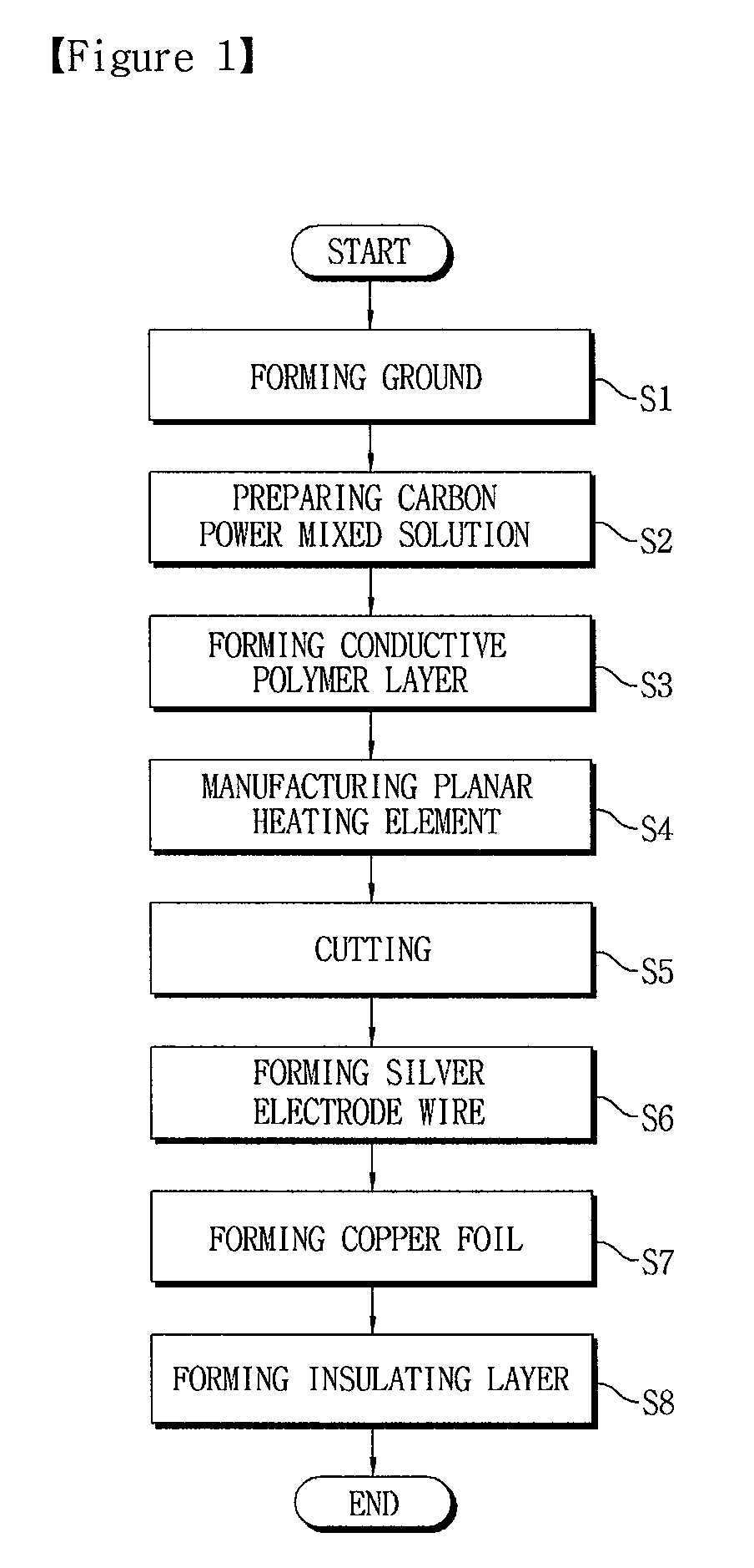
[0065]FIG. 1 shows a flowchart for explaining a method for manufacturing a planar heating element using carbon micro-fibers according to the first embodiment of the present invention. FIG. 2 shows a plan view and a cross-sectional view of a ground with prepared and cultured carbon micro-fibers according to the method for manufacturing a planar heating eleme...

second embodiment

[0114]Hereinafter, a method for manufacturing a planar heating element using carbon micro-fibers according to the present invention will be described in detail with reference to the accompanying drawings.

[0115]In the following description of the present invention, detailed description of related function and configuration is omitted when it can make main points of the present invention vague. The following terms are defined by considering the function of the present invention and they can be changed according to an intention of a user or custom. Thus, definition of terms should be made based on the content of the whole specification.

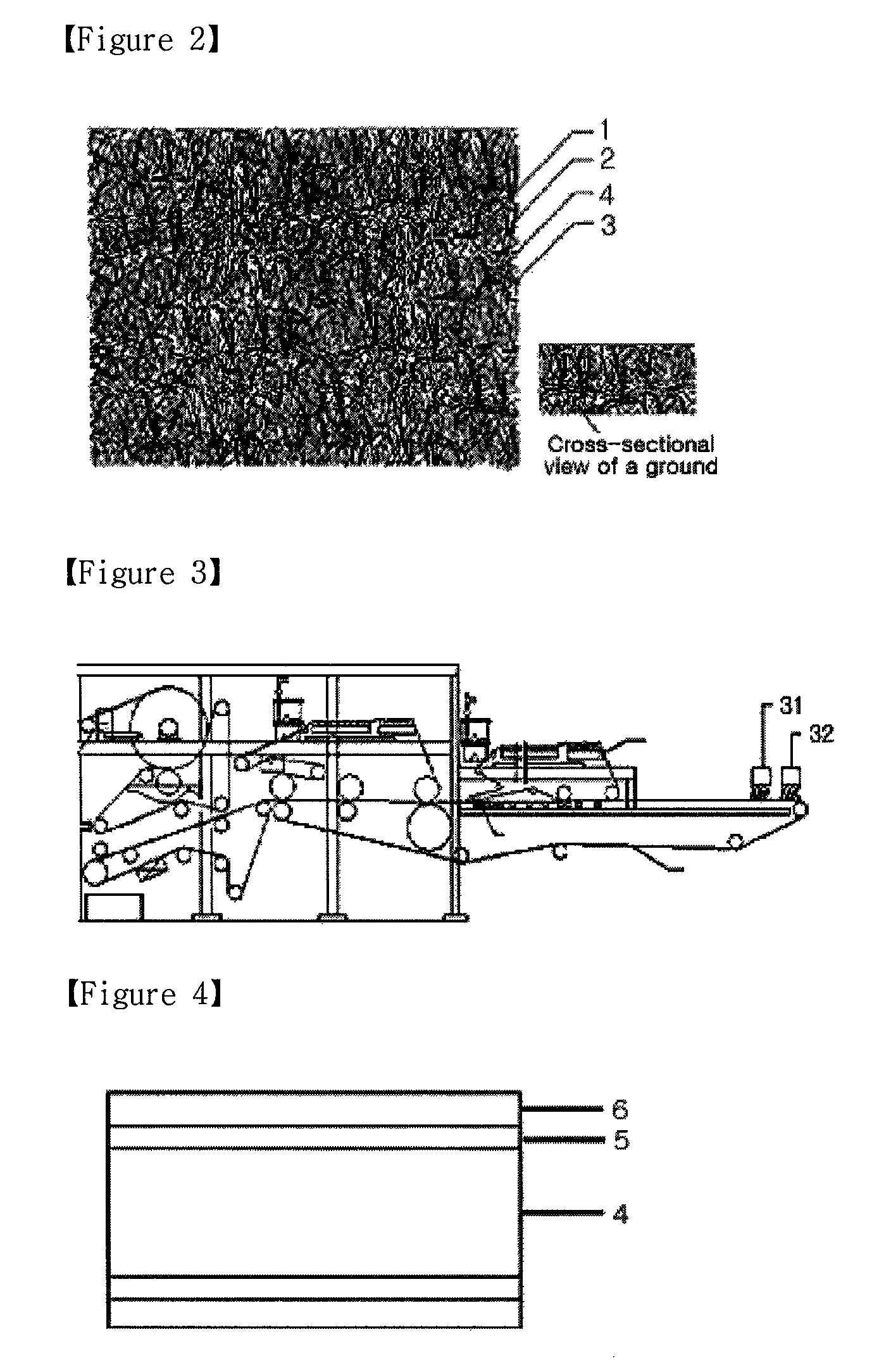
[0116]FIG. 9 shows a diagram showing a planar heating element manufacturing apparatus using carbon micro-fibers according to the second embodiment of the present invention. FIG. 10 shows a primary ground in the method for manufacturing a planar heating element using carbon micro-fibers according to the second embodiment of the present invention. FIG. 11 ...


PUM

PropertyMeasurementUnit
thicknessaaaaaaaaaa
lengthaaaaaaaaaa
widthaaaaaaaaaa

Abstract

A planar heating element using for carbon micro-fibers and its manufacturing method have developed. The high-resistant carbon micro-fibers and carbon powder are efficiently coated to completely replace a conventional heating element using resistance heat of a nichrome wire. A single heating element is possibly formed to have a large width and an ultra thin heating element without temperature restriction by overcoming drawbacks of a carbon powder printed heating element serving as an initial module of the planar heating element. Thus, it is possible to produce the various convenient heating elements or heating modules using DC and AC electricity without restriction by solving problems in installation and use, for example, space restriction, thereby various convenient heating elements.

Description

BACKGROUND OF THE INVENTION[0001]1. Field of the Invention[0002]The present invention relates to a planar heating element using carbon micro-fibers and a method for manufacturing the same, and more particularly to a planar heating element using carbon micro-fibers and a method for manufacturing the same capable of realizing uniform temperature distribution of the entire heating element, preventing an increase in the temperature due to reduction of local resistance, prolonging a life of the heating element, and maintaining performance even when a local external load is exerted by forming a ground of the planar heating element using mixed carbon micro-fibers, pulp and synthetic fibers, and then coating carbon powder mixed with a conductive polymer on both surfaces of the ground.[0003]2. Description of the Related Prior Art[0004]Generally, a planar heating element made of carbon is used as a residential heating material since it is safe, makes no noises and eliminates the danger of an ...

Claims


Application Information

Patent Timeline
Patent Type & Authority Patents(United States)
IPC IPC(8): B29C65/48H05B3/34
CPCH05B3/145H05B3/146H05B3/342H05B2203/011Y10T156/1093H05B2203/017H05B2203/034H05B2214/04H05B2203/013H05B3/20H05B3/34
Inventor JUNG, IN
Owner NAOS
Why Eureka
Try Eureka