Multi-faceted tileable detector for volumetric computed tomography imaging

a computed tomography and detector technology, applied in tomography, instruments, applications, etc., can solve the problems of significant drawback to image quality provided by 256 slice detectors and beyond, degradation in detector performance, and artifacts in reconstructed ct images, so as to minimize image data degradation, increase slice acquisition, and minimize the effect of image data degradation

Active Publication Date: 2012-06-19
GENERAL ELECTRIC CO
View PDF16 Cites 9 Cited by
  • Summary
  • Abstract
  • Description
  • Claims
  • Application Information

AI Technical Summary

Benefits of technology

[0008]The invention is a directed apparatus for CT image acquisition that provides for increased slice acquisition with minimal image data degradation. A detector module having a multi-faceted construction is provided, with a plurality of facets on the module being constructed so as to be oriented at differing angles relative to an x-ray source focal spot. Detector sub-modules are positioned on the angled facets to receive x-rays attenuated by an object and to convert the x-rays to electrical signals, with the angling of the detector sub-modules relative to the focal spot serving to minimize image data degradation.

Problems solved by technology

However, increasing the coverage of the detector in the Z-axis beyond 64 slices up to 256 slices might lead to a degradation in performance of the detector.
At a certain position along the Z-axis, the primary beam of x-rays will cross two contiguous pixels in the Z-direction, thereby inducing a significant crosstalk from slice to slice, spectral non-linearity because of the beam hardening with the pixels, slice profile degradation, and Modulation transfer function (MTF) deterioration, collectively known as “parallax.” This parallax caused by the increased number of slices can lead to artifacts being present in the reconstructed CT image, thereby presenting a significant drawback to image quality provided by a 256 slice detector and beyond.

Method used


Image

  • Multi-faceted tileable detector for volumetric computed tomography imaging
  • Multi-faceted tileable detector for volumetric computed tomography imaging
  • Multi-faceted tileable detector for volumetric computed tomography imaging

Examples


Embodiment Construction

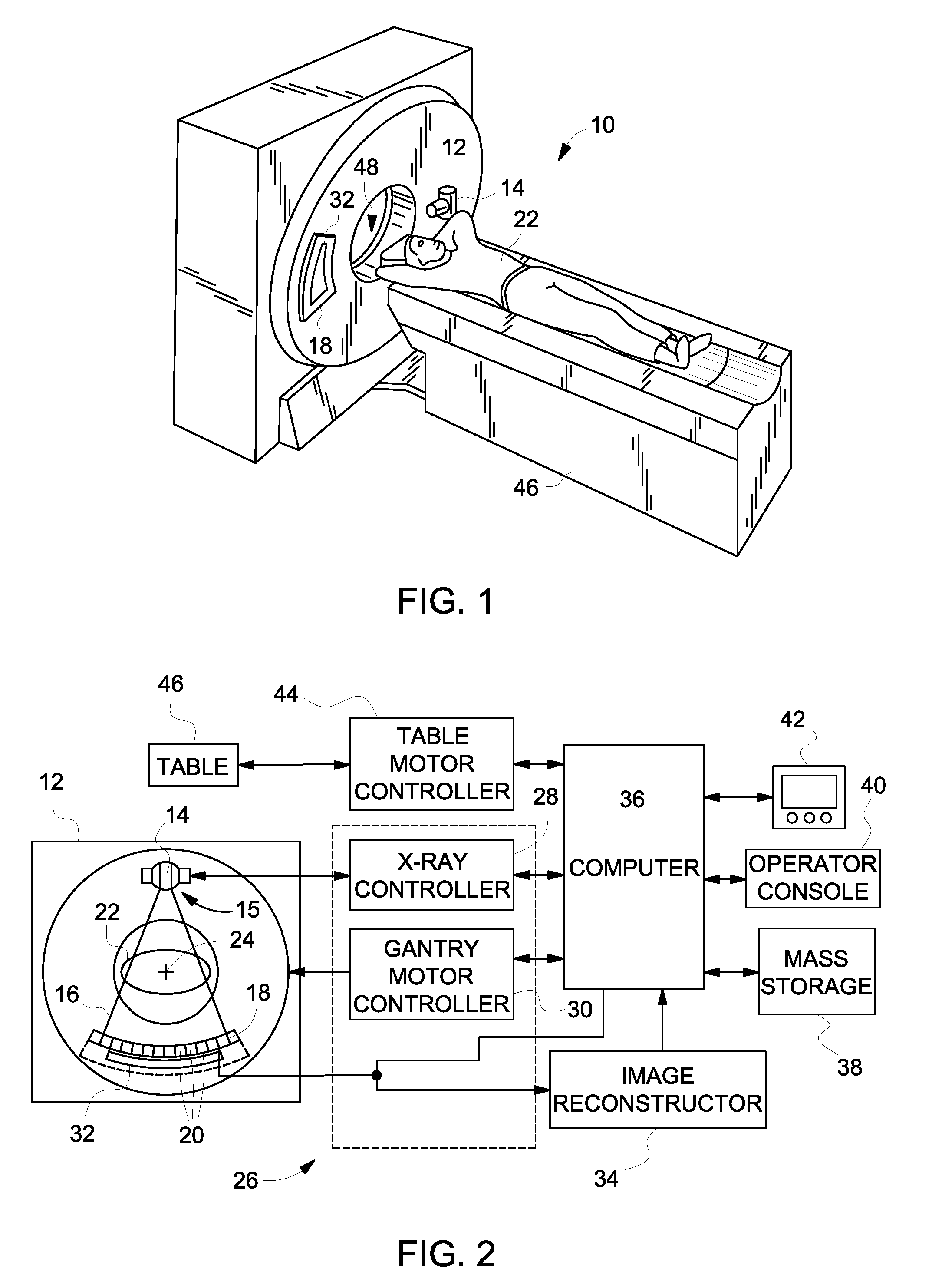
[0021]The operating environment of the invention is described with respect to a 256 slice computed tomography (CT) system. However, as will be explained in detail below, the invention is equally applicable for use with other multi-slice configurations between sixty-four slices and 256 slices, and beyond. Moreover, the invention will be described with respect to the detection and conversion of x-rays. However, one skilled in the art will further appreciate that the invention is equally applicable for the detection and conversion of other high frequency electromagnetic energy. The invention will be described with respect to a “third generation” CT scanner, but is equally applicable with other CT systems.

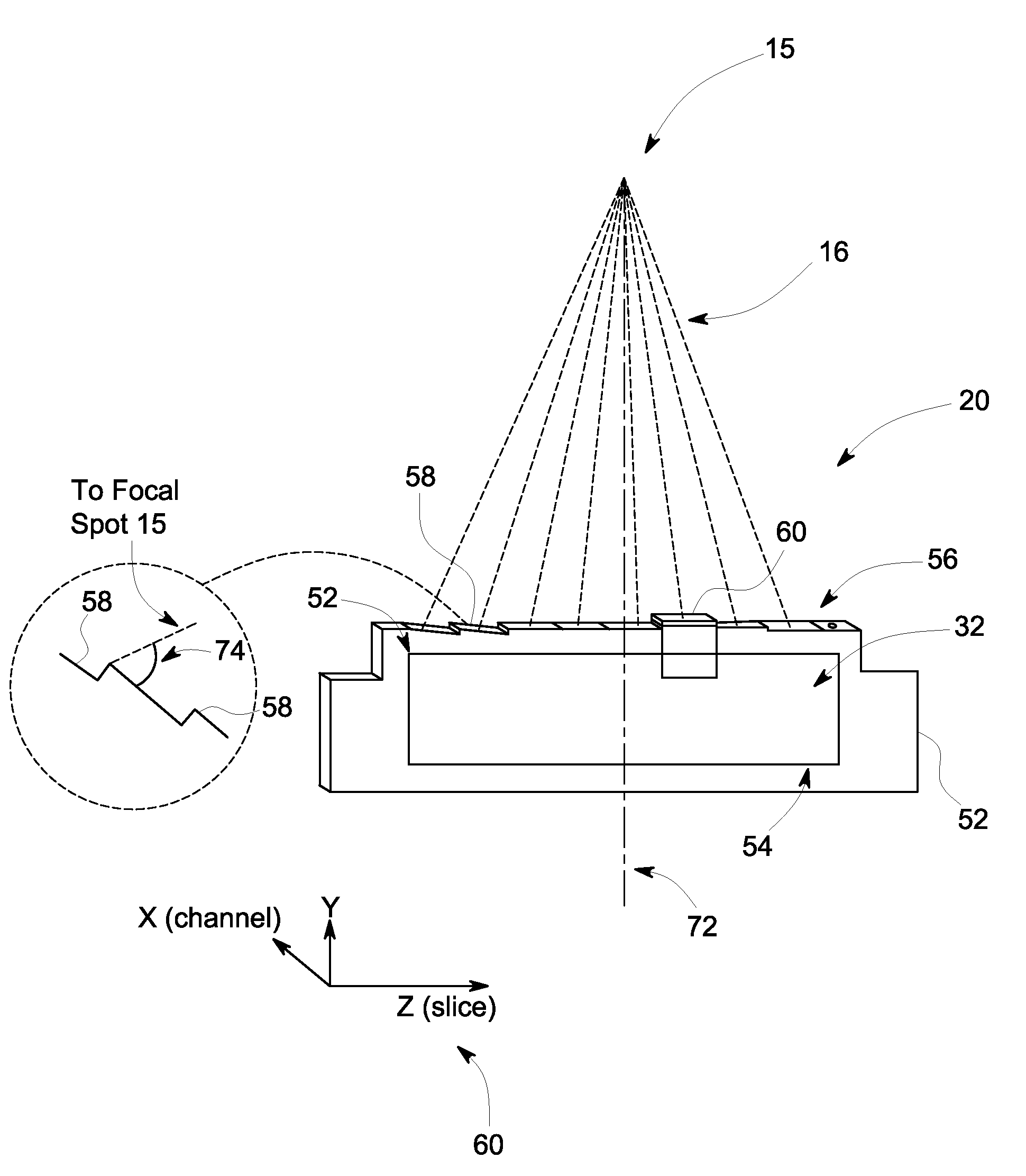
[0022]Referring to FIGS. 1 and 2, a computed tomography (CT) imaging system 10 is shown as including a gantry 12 representative of a “third generation” CT scanner. Gantry 12 has an x-ray source 14 that projects a beam of x-rays from a focal spot 15 of the source 14 and toward a detecto...


PUM


Abstract

A system and method for CT image acquisition with increased slice acquisition and minimal image data degradation is provided. The system includes an x-ray projection source positioned that projects a cone beam of x-rays from a focal spot of the x-ray projection source toward an object and a plurality of detector modules positioned on the rotatable gantry to receive x-rays attenuated by the object. Each of the detector modules includes a module frame having a top surface that includes a plurality of facets formed thereon constructed so as to be oriented at differing angles relative to the focal spot and a plurality of sub-modules positioned on the plurality of facets to receive the x-rays attenuated by the object and to convert the x-rays to electrical signals, with each sub-module being oriented at an angle relative to the focal spot based on a respective facet on which the sub-module is mounted.

Description

BACKGROUND OF THE INVENTION[0001]Embodiments of the invention relate generally to radiographic detectors for diagnostic imaging and, more particularly, to a Computed Tomography (CT) detector module having a multi-faceted construction that provides for increased slice acquisition with minimal image data degradation.[0002]Typically, in computed tomography (CT) imaging systems, an x-ray source emits a fan-shaped beam toward a subject or object, such as a patient or a piece of luggage. Hereinafter, the terms “subject” and “object” shall include anything capable of being imaged. The beam, after being attenuated by the subject, impinges upon an array of radiation detectors. The intensity of the attenuated beam radiation received at the detector array is typically dependent upon the attenuation of the x-ray beam by the subject. Each detector element of the detector array produces a separate electrical signal indicative of the attenuated beam received by each detector element. The electrica...

Claims


Application Information

Patent Timeline
Patent Type & Authority Patents(United States)
IPC IPC(8): A61B6/00
CPCA61B6/00A61B6/032A61B6/5258A61B6/4266A61B6/42A61B6/503
Inventor IKHLEF, ABDELAZIZ
Owner GENERAL ELECTRIC CO
Why Eureka
Try Eureka