Apparatus and method for artificial reverberation

a technology of artificial reverb and apparatus, applied in the field of audio signal processing, to achieve the effect of reducing the number of delay lines, high quality, and cost-effectiveness

Active Publication Date: 2012-06-19
NEUNABER BRIAN C
View PDF4 Cites 2 Cited by
  • Summary
  • Abstract
  • Description
  • Claims
  • Application Information

AI Technical Summary

Benefits of technology

[0022]In accordance with the present invention, the preferred embodiment represents an apparatus and method for artificial reverberation comprising a plurality of parallel delay elements interconnected using a FDN. FIG. 3 shows a preferred embodiment signal flow with FIG. 3a being a slight modification thereto. One or more input signals are summed to one or more signal nodes before the delay elements. One or more output signals are taken from the output of one or more delay elements. Output signals are taken from delay elements that do not have input signals applied to them. Using this method, the echo density of the reverberation is allowed to build slightly before the signal is output from the FDN, which further eliminates the need for an additional pre-delay element. Also, since the input signal must pass through at least two comb filters before reaching an output, this method improves upon the sometimes-unpleasant characteristic sound of a typical FDN reverberator. That is, the two comb filters diffuse the direct-path comb filtering present in the prior art. This improvement results in a more natural sounding FDN reverberator.
[0023]As seen in FIG. 3a, this aspect of the invention is generalized by the following equation:|bi|+|ci|≈1Where bi is the gain applied to an input into the ith delay element (or corresponding summation element) and ci is the gain applied to an output from the ith delay output, as defined by the Jot and Chaigne Equation. Using this expression, the input-to-output gain through any single delay path is|bi|×|ci|which minimizes the direct contribution of any one comb filter by constraining it to a maximum value of 0.52=0.25, while also mitigating the increase in pre-delay that results from not injecting into and summing from all delay paths. Typically, the aforesaid equation is further qualified by stating that at least one value of bi≈1 and one value of bi≈0 (i.e. ci≈1) such that the direct input-to-output gain through any single delay path is 0. That is, a second series combination output (i.e. filter and delay element) which feeds the output port has no direct input signal but instead must receive its input from a summation of one or more first series combination outputs (i.e. first filters and delay elements). The constraint of the equation further mitigates the effect noted by Jot of the “spurious echo” at a period equal to the sum of delays.
[0026]Another aspect of the present invention addresses the need for an inexpensive, high quality reverberator by combining digital and analog electronics. Artificial reverberation is created using a combination of delays, filters, and feedback. In this invention, the delay is implemented using digital electronics. Filtering and feedback, which consists of gain and summation, are preferably implemented using analog circuitry. The use of this combination of technologies results in a very cost-effective solution.
[0027]The preferred embodiment of the present art utilizes inexpensive, monolithic digital-delay integrated circuits for the delay lines and replaces the digital computational logic with analog circuitry. All filtering, summation, and gain is performed by inexpensive analog circuitry. Furthermore, by carefully selecting the delay times, modulating one or more of these delay times, and taking the output signal from delay lines exclusive of delay lines to which input is directly applied, the number of delay lines can be reduced while maintaining the desired audio quality.

Problems solved by technology

Also, since the input signal must pass through at least two comb filters before reaching an output, this method improves upon the sometimes-unpleasant characteristic sound of a typical FDN reverberator.

Method used


Image

  • Apparatus and method for artificial reverberation
  • Apparatus and method for artificial reverberation
  • Apparatus and method for artificial reverberation

Examples


Embodiment Construction

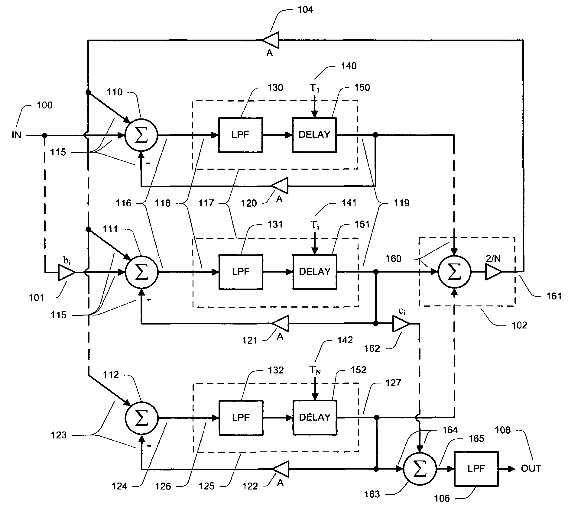
[0037]Referring now to the drawings, there is shown in FIGS. 3, 5, &6 a preferred embodiment of the apparatus and method for artificial reverberation 10 and in FIGS. 3a &4 a first alternative embodiment of the apparatus and method for artificial reverberation 10. The apparatus and method 10 allows electronic creation of artificial reverberation without the requirement for digital signal processors or the extensive engineering time and labor associated therewith. The present art minimizes cost by combining digital delay elements with an analog feedback network and maximizes sound quality while using a minimum of delay elements.

[0038]FIG. 3 illustrates a block signal flow diagram of the preferred embodiment of the present art. Although a total of three delay elements are shown, any number of delay elements greater than one is within the scope of this invention. An input signal is first applied or fed to input signal port 100 and then applied or fed to input summing nodes 110 and 111 a...


PUM


Abstract

An apparatus and method for artificial reverberation having one or more input summing nodes receiving an input signal and which each feed a first series of delay elements and the output of which is thereafter summed, weighted, and fed back to the input summing nodes. Also, a feedback summing node which further feeds a second delay element which feeds an output with a signal which has multi-dimensional or multi-delay reverberation relative to the input signal. An alternative embodiment further feeds one or more of the first delay element outputs weighted via an output gain to an output summing node which also sums the output of the second delay element and provides a summed output having a multi-dimensional or multi-delay reverberation. The embodiment is easily and economically implemented via conventional integrated electronic circuits, a combination of analog and digital electronics, digital signal processors, microprocessors, micro-controllers, or computer algorithms.

Description

[0001]This application claims priority of U.S. Provisional Patent Application No. 60 / 937,817, filed Jun. 30, 2007, entitled Apparatus and Method for Artificial Reverberation.BACKGROUND OF THE INVENTION[0002]The present invention relates to the processing of an audio signal for the simulation of acoustic reverberation in general and more particularly for application to musical instruments and vocals. The present art is especially adaptable to the electronic processing of audio signals in order to add user desired reverberation effect(s). Artificial reverberation simulates the ambience of a sound within an enclosed space, such as a large room or music hall.[0003]Reverberation is commonly added to audio signals to increase the listener's perception of ambience and spaciousness. Natural reverberation occurs when a sound is radiated within an enclosed space; the sound reflects off of the various walls and objects within the room, traveling back to the listener later in time. This reflect...

Claims


Application Information

Patent Timeline
Patent Type & Authority Patents(United States)
IPC IPC(8): H03G3/00
CPCH04S1/002
Inventor NEUNABER, BRIAN C.
Owner NEUNABER BRIAN C
Why Eureka
Try Eureka