Flip-chip semiconductor package and chip carrier for preventing corner delamination

a technology of semiconductor packaging and chip carrier, which is applied in the direction of semiconductor devices, semiconductor/solid-state device details, electrical apparatus, etc., can solve the problems of exposing or teaching, affecting the electrical functions of solder bumps b>13/b> badly, and low-k dielectric materials that have a hard and brittle characteristic and are therefore susceptible to delamination

Active Publication Date: 2012-06-26
SILICONWARE PRECISION IND CO LTD
View PDF6 Cites 1 Cited by
  • Summary
  • Abstract
  • Description
  • Claims
  • Application Information

AI Technical Summary

Benefits of technology

[0010]In light of the foregoing drawbacks of the prior art, a primary objective of the present invention is to provide a flip-chip semiconductor package and a chip carrier thereof, which can prevent underfill-chip delamination, underfill-substrate delamination, and delamination within a semiconductor chip.
[0011]Another objective of the present invention is to provide a flip-chip semiconductor package and a chip carrier thereof, which can provide a superior support for a semiconductor chip as well as protect solder bumps.
[0012]Yet another objective of the present invention is to provide a flip-chip semiconductor package and a chip carrier thereof, which can reduce a tremendous amount of time and money spent on researching an underfill capable of avoiding delamination due to a mismatch of coefficient of thermal expansion between a semiconductor chip and a substrate.
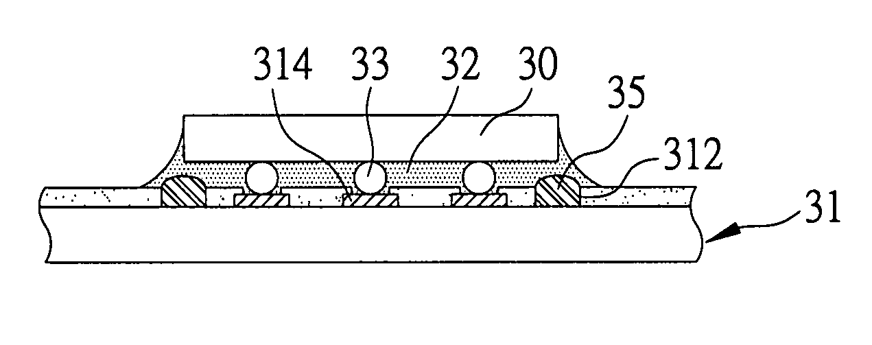
[0015]For instance, the chip carrier may be a substrate and the groove may be formed in a solder mask on the substrate. Moreover, the groove may be formed in position along the periphery of the chip-mounting area or at the four corners thereof. Accordingly, when a filler of low Young's modulus is filled into the groove, the filler is disposed in position corresponding to at least a corner or a side of the flip chip mounted on the chip-mounting area, so as to absorb and eliminate thermal stress, preventing occurrence of corner delamination of the flip chip. In addition, the filler may be made of any material having a glass transition temperature Tg of less than 80° C., or a Young's modulus of less than 2000 Mpa at room temperature (25° C.).
[0016]Accordingly, the present invention discloses a flip-chip semiconductor package and a chip carrier thereof. One of the main features of the present invention is that the chip carrier comprises a groove formed in position corresponding to a chip-mounting area, wherein the groove may be formed in position corresponding to the periphery of the chip-mounting area or the corners thereof. Moreover, a filler of low Young's modulus is employed to fill the groove so as to protect corners of a flip chip mounted on the chip-mounting area above the filler as well as absorbing and eliminating thermal stress. In addition, an underfill is employed to interpose between the flip chip and the chip carrier and among a plurality of solder bumps so as to protect the solder bumps and provide support for the flip chip, thereby preventing delamination between the underfill and the flip chip, delamination between the underfill and the chip carrier, and delamination within the flip chip. As a result, the present invention can save a tremendous amount of time and money in researching and producing a suitable underfill for each of different kinds of semiconductor packages and solving delamination problems.

Problems solved by technology

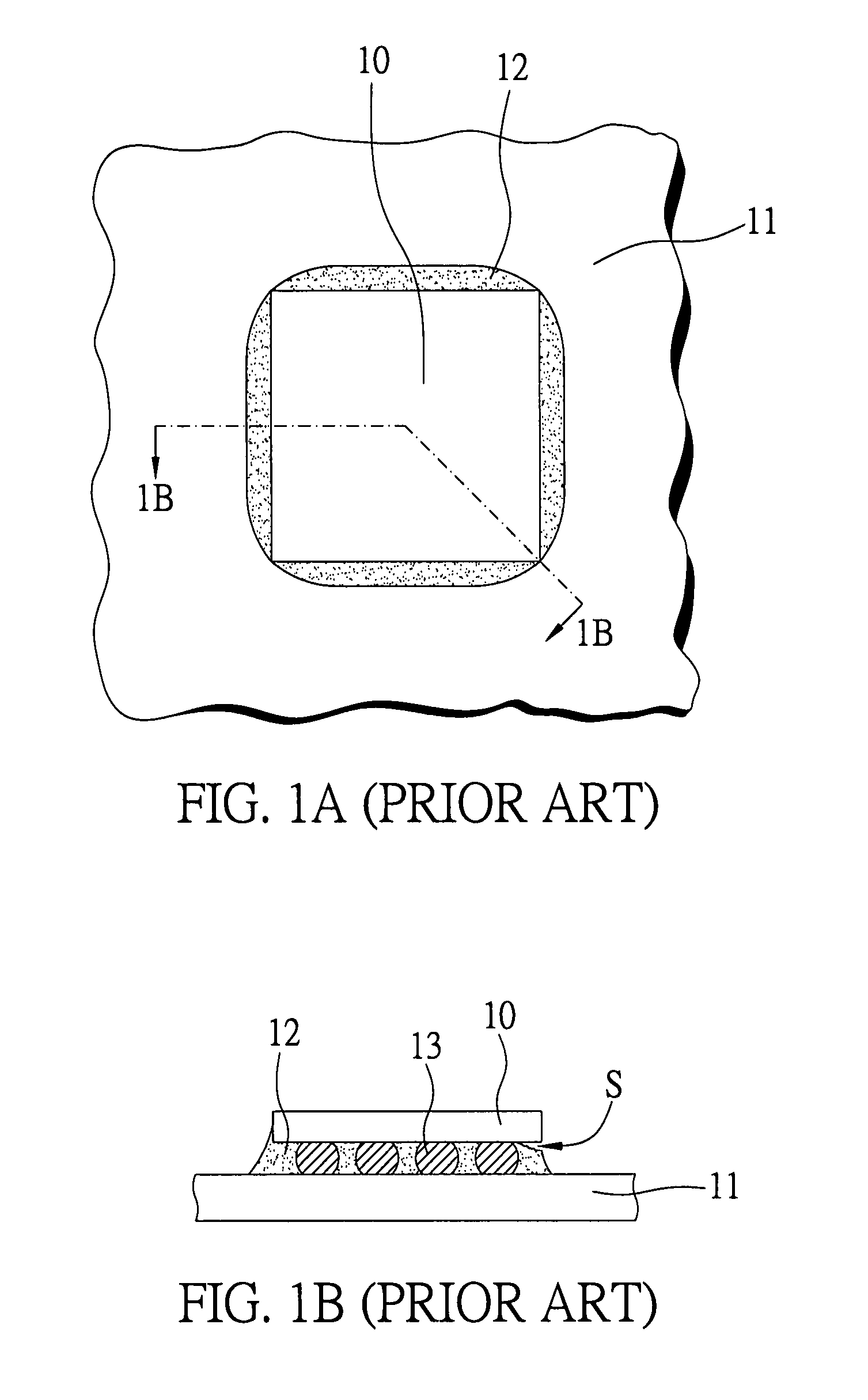
Moreover, if such peripheral delamination is turned into a more severe situation, the delamination may be expanded from the peripheral to the center of the underfill 12, thereby affecting the electrical functions of the solder bumps 13 badly.
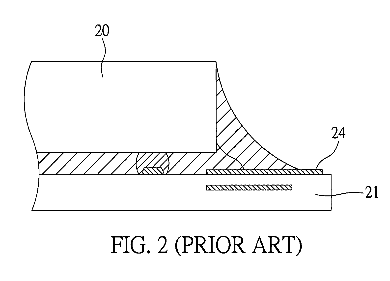
However, the low-K dielectric material typically has a hard and brittle characteristic and therefore is susceptible to delamination, because the low-K dielectric material cannot efficiently absorb and eliminate thermal stress generated during fabrication processes.
Nevertheless, U.S. Pat. No. 6,734,567 does not disclose or teach a way to prevent delamination between the underfill and the flip chip 20 and delamination inside the flip chip 20.
However, simply applying an underfill with low Young's modulus cannot provide a strong and sufficient supporting strength for the solder bumps.
On the other hand, an underfill with high Young's modulus may provide a greater supporting strength for the solder bumps, but the underfill with high Young's modulus makes the flip chip subject to thermal stress and therefore results in delamination.
Accordingly, a lot of researches and studies have to be done in order to find underfills suitable for connecting chips and substrates of different sizes and kinds, however these researches and studies are often laborious, cost-consuming, time-consuming and test-based, thereby leading to a prolonged fabrication process and higher fabrication costs.
Solutions to these problems have been long sought but prior developments have not taught or suggested any solutions and, thus, solutions to these problems have long eluded those skilled in the art.

Method used


Image

  • Flip-chip semiconductor package and chip carrier for preventing corner delamination
  • Flip-chip semiconductor package and chip carrier for preventing corner delamination
  • Flip-chip semiconductor package and chip carrier for preventing corner delamination

Examples


Embodiment Construction

[0025]In the following description, numerous specific details are given to provide a thorough understanding of the invention. However, it will be apparent that the invention may be practiced without these specific details. In order to avoid obscuring the present invention, some well-known configurations and process steps are not disclosed in detail.

[0026]Likewise, the drawings showing embodiments of the structure are semi-diagrammatic and not to scale and, particularly, some of the dimensions are for the clarity of presentation and are shown greatly exaggerated in the drawing. Similarly, although the views in the drawings for ease of description generally show similar orientations, this depiction in the drawings is arbitrary for the most part. Generally, the invention can be operated in any orientation.

[0027]For expository purposes, the term “horizontal” as used herein is defined as a plane parallel to the plane or surface of the substrate, regardless of its orientation. The term “v...


PUM


Abstract

The present invention discloses a flip-chip semiconductor package and a chip carrier thereof. The chip carrier includes a groove formed around a chip-mounting area. The groove may be formed along a periphery of the chip-mounting area or at corners thereof. The groove is filled with a filler of low Young's modulus so as to absorb and eliminate thermal stress, thereby preventing delamination between an underfill and a flip chip mounted on the chip-mounting area.

Description

FIELD OF THE INVENTION[0001]The present invention relates to semiconductor packages and chip carriers thereof, and more particularly, to a flip-chip semiconductor package and a chip carrier thereof.BACKGROUND OF THE INVENTION[0002]A flip-chip semiconductor package is a type of semiconductor package with its electrical connection being established by means of flip-chip technology. For example, in a flip-chip semiconductor package, an active surface of at least one semiconductor chip is attached to and electrically connected to a substrate via a plurality of solder bumps. Recently, such design has become a dominating packaging technique, because such design not only can reduce package size and decrease the ratio of the semiconductor chip to the substrate, it can also reduce impedance and enhance electrical functions as it does not require the use of bonding wires.[0003]Referring to FIGS. 1A and 1B, a prior-art flip-chip semiconductor package is disclosed. First, a flip chip 10 is moun...

Claims


Application Information

Patent Timeline
Patent Type & Authority Patents(United States)
IPC IPC(8): H01L23/29
CPCH01L21/563H01L24/31H01L2224/16225H01L2224/73203H01L2224/83951H01L2924/01082H01L2924/19041H01L2924/19043H01L2924/3011H01L2924/01006H01L2924/01019H01L2924/01033H01L2224/32225H01L2224/73204H01L2924/00H01L2924/351
Inventor TZENG, YUAN-LINKAO, NAI-HAOLAI, JENG-YUANWANG, YU-POHSIAO, CHENG-HSU
Owner SILICONWARE PRECISION IND CO LTD
Why Eureka
Try Eureka