Greening system

a technology of greening system and greening valve, which is applied in the field of greening system to achieve the effect of high breathabl

Active Publication Date: 2012-07-03
KAWADA CONSTR
View PDF75 Cites 16 Cited by
  • Summary
  • Abstract
  • Description
  • Claims
  • Application Information

AI Technical Summary

Benefits of technology

[0057]As explained above, in an embodiment of the greening system of the present disclosure, the container can be separated by a perforated partition panel into upper and lower zones to use the lower half as a water storage and the soil layer carried on the upper face contains or laminates porous-structured material formed of continuous fine pores for absorbing water evaporating from the water storage, supplying plants with absorbed water, while letting extra water such as rainwater pass by to work as a filter to drain out e.g. acid rainwater as clean water, alleviating affections to environment or to human bodies.
[0058]The greening system according to the present disclosure, comprising a structure with underground-embedded water storage is applicable also e.g. to large-scale greening of streets, enabling rainwater to be guided into the water storage.
[0026]To solve the above problems, the present invention relates to a greening system, with a soil layer formed for greening plant to grow in a bottomed container opened on top, equipped with water regulator feeding water necessary for the plant to grow and draining out excess water, characterized in that the container, separated e.g. by a perforated partition panel into upper and lower zones, has drain holes opened on sides on the upper face of the partition panel, a water storage of watertight structure inside the half lower than the partition panel, materials of porous structure formed of continuous fine pores for absorbing water transported from the water storage by evaporation or difference in humidity being contained or laminated in the soil layer placed on the partition panel.
[0070]In the greening system of an exemplary embodiment, purified water is used efficiently thanks to the porous-structured material and the soil layer carried by the water-storing container for greening plants to grow, enabling plants to grow only with natural rainfall, without any particular irrigation, even for trees to grow in roadside areas lacking in amount of soil or even for flowers needing relatively much water to grow in areas limited in water supply.
[0043]The water storage in a greening system in accordance with this disclosure may have a capacity for storing an amount of water necessary for the plant to grow with natural rainfall during a year. The soil layer is adapted to have a large water-retaining capacity letting less water evaporate, while water at the water storage is consumed only as absorbed e.g. by charcoal. No other irrigator is needed here, only storing natural rainfall, as the water storage stores an amount necessary for the plants to grow. Further, there is no need for periodical watering if in usual climates. For example, the depth of the water storage should be 5 cm to put a soil layer 5 cm thick.
[0062]Porous-structured material in an embodiment of the greening system may be carbonized plywood or the like wasted in construction work. It is not only ecological but also advantageous in plate-like charcoal easily filling the holes of the partition panel, preventing unnecessary things from falling from the soil layer to the water storage.
[0063]The soil layer in an embodiment of the greening system may be is a woody light soil layer based on mixture of charcoal and humus woodchips having a large water capacity letting less water evaporate into the air, enabling plants to grow with a little water supply.
[0064]A charcoal layer is interposed between the soil layer and the partition panel in an embodiment of the greening system retain a constant amount of water, absorbing and releasing water stepwise, limiting unnecessary water supply, with effects of feeding plants with water, fertilizer or cooling the soil, thanks to water moving by difference in relative humidity in the respective layers from the water storage to the surface of the plant and to capillarity of evaporated water.
[0062]Porous-structured material in an embodiment of the greening system may be carbonized plywood or the like wasted in construction work. It is not only ecological but also advantageous in plate-like charcoal easily filling the holes of the partition panel, preventing unnecessary things from falling from the soil layer to the water storage.
[0066]The greening system may have water storage of sufficient capacity to store a necessary amount of water for the plants to grow with natural rainfall during a year, only needing to store natural rainwater and no other particular irrigator, even without periodical watering if in usual climate.
[0067]In the greening system of an exemplary embodiment, a plurality of containers are placed on crossbeams as supported on girders constituting a roof slab for drain holes to be communicated with one another in order to prevent the containers from weighing on the floor of the rooftop slab lacking in tolerance of load. Then, the loading is directly imposed on the main members of the structure of the building, requiring no particular reinforcement, if the members are strong enough. As the drains are communicated with each other, extra water is discharged quickly and it is of no need to reinforce waterproofing of the floor. It is therefore easily applicable to existing buildings, regardless of the size of scale.
[0068]A level-adjusting plate is interposed between the plurality of containers and the crossbeams, also fixing bulk-increasing band around the container, in an embodiment of the greening system, enabling variation in thickness and height of the soil layer and utilization as a plane all together, making it walkable e.g. planted with grass, allowing not only bushes like azaleas but also middle-sized trees to be planted, also enabling formation of slopes to construct a full-blown garden on a rooftop of a building.
[0069]In an exemplary embodiment of the greening system, extra water overflows by notches to assure the soil layer and the water surface to be separated from each other. Then, overflowing water follows a vertical gutter to flow down on the foundation and can flow down smoothly to outside via push-ups for drainage. The inner wall is reinforced to support the loading of the soil layer, while water dripping down into the water storing container is made uniform thanks to the presence of an opening Rainwater passing through the soil layer drips down into the water-storing container through holes opened on the lid, while the porous-structured material absorbs water evaporating from the water-storing container through the same holes.
[0070]In the greening system of an exemplary embodiment, purified water is used efficiently thanks to the porous-structured material and the soil layer carried by the water-storing container for greening plants to grow, enabling plants to grow only with natural rainfall, without any particular irrigation, even for trees to grow in roadside areas lacking in amount of soil or even for flowers needing relatively much water to grow in areas limited in water supply.
[0071]In the greening system of an exemplary embodiment, an underground headrace channel is used as an outflux of purified water, contributing to improvement of water quality inside the headrace as well as utilizing water vapor inside the headrace for plants to grow.

Problems solved by technology

Another problem to solve is to offer a greening system even for trees planted e.g. at roadside planting strips limited in amount of soil or for flowers needing relatively much water, planted in areas limited in water supply, to grow only with natural rainfall, without any particular irrigation.

Method used


Image

  • Greening system
  • Greening system
  • Greening system

Examples


Embodiment Construction

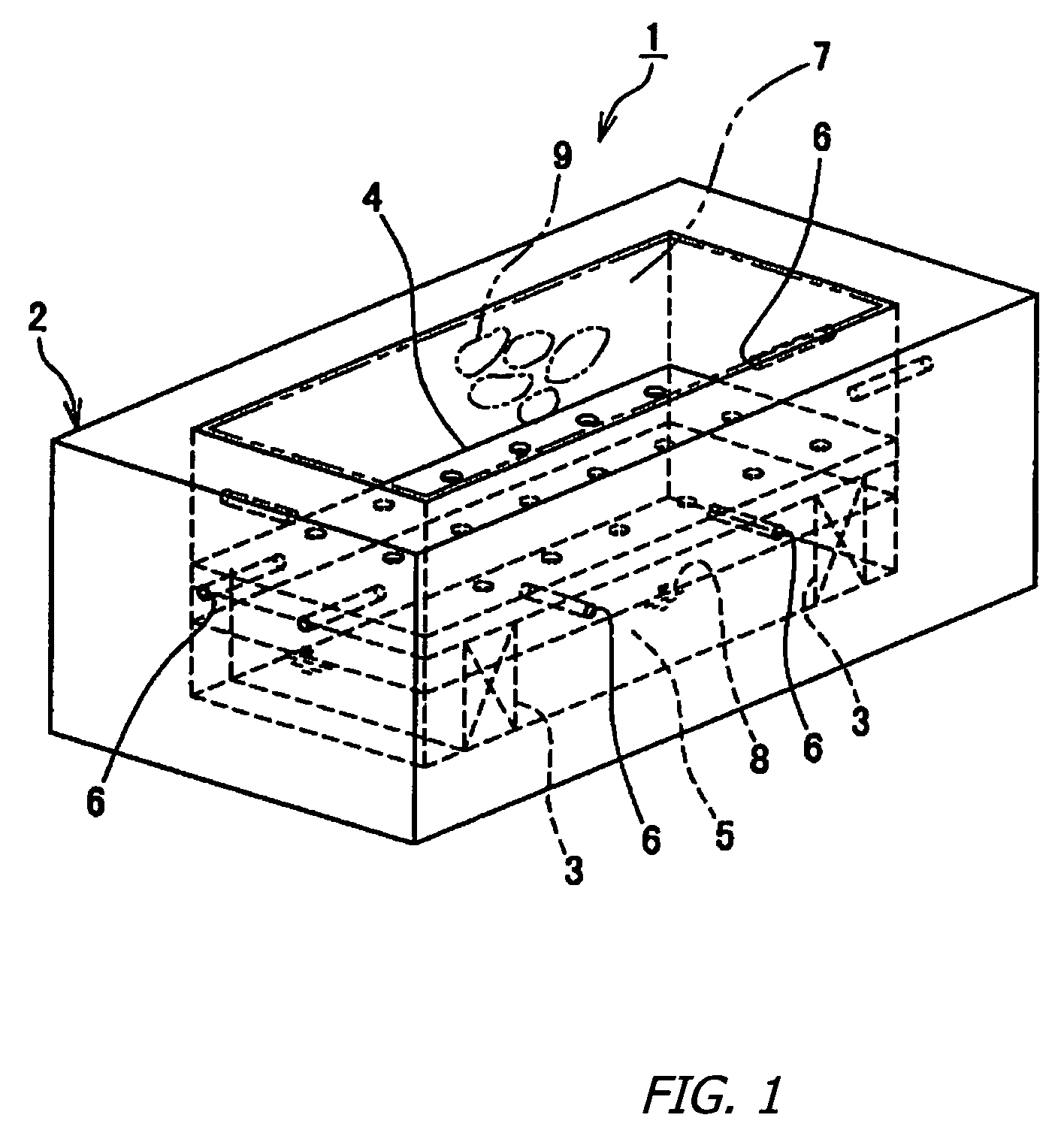
[0099]The mode of realization of the invention will be explained in detail, referring to drawings attached herewith. FIG. 1 shows a perspective view of a planting container on which a greening system is based. Planting container 1 comprises styrene foam box 2 opened on top and with stickers 3 at bottom carrying perforated partition panel 4 of polyvinyl chloride between the top and bottom. The container is covered on the inner surface with non-illustrated waterproofing sheet below the partition panel 4 to form watertight water storage 5. Planting container 1 is sized in principle to be 100 cm wide×50 cm deep×20 cm high, made of members 10 cm thick, but can be smaller or larger.

[0100]The container has a necessary number of drain holes 6 opened on sides immediately above partition panel 4 for quickly draining out water in excess over partition panel 4. Then, charcoal pieces 9 are embedded in soil layer 7 placed on partition panel 4 to absorb water evaporating from water 8 stored in wat...


PUM


Abstract

A greening system us disclosed for enabling plants / vegetation to grow only with natural rainfall, without any particular irrigation facilities, enabling a full-blown garden to be constructed on building rooftops, minimizing the applicable loads on the building, and free from the risk of leakage. Planting container 1 comprises box 2 with stickers 3 to carry perforated partition panel 4. The lower half of the container is constituted as water storage 5, and drain holes 6 are opened on sides of the container. Soil layer 7 placed on partition panel 4 is formed of light woody soil-based on charcoal 9 and humus timber chips for absorbing moisture transported from the water 8 stored in water storage 5 by evaporation or difference in humidity, to have a large water capacity letting less water evaporate into the air. Charcoal 9 absorbs water from the air inside the lower half of the container to water the plants. Water storage 5 assures an amount of water necessary for plants to grow.

Description

RELATED APPLICATIONS[0001]This application claims priority of PCT application number PCT / JP2004 / 008189, which was filed on Jun. 11, 2004; which claims priority to JP2003 / 0169837, which was filed on Jun. 13, 2003; and JP2003 / 432251, JP2003 / 432252, JP2003 / 432253, and JP2003 / 432254, all of which were filed on Dec. 26, 2003, all of which are hereby incorporated by reference in their entirety.BACKGROUND[0002]1. Field[0003]The present invention relates to a greening system enabling plants to effectively grow with only minimal natural rainfall or limited irrigation even in the absence of any particular irrigator by making use of water absorbing and releasing capabilities of porous structures such as charcoal perforated with continuous fine capillary tubes, advantageously applicable to greening of roofs, surroundings of buildings, upper surfaces of underground structures, paved streets and / or areas usually lacking in greenery.[0004]2. General Background[0005]As needed for better urban envir...

Claims


Application Information

Patent Timeline
Patent Type & Authority Patents(United States)
IPC IPC(8): A01G9/02A01G27/02
CPCA01G27/02A01G9/02
Inventor FURUMURA, TAKASHIFUKUHARA, TOSHIAKIKAWADA, SHINICHI
Owner KAWADA CONSTR
Why Eureka
Try Eureka