Dishing and defect control of chemical mechanical polishing using real-time adjustable additive delivery

a technology of chemical mechanical polishing and defect control, applied in the direction of grinding machine components, manufacturing tools, lapping machines, etc., can solve the problem of one or more concave depressions, and achieve the effect of uniform removal

Active Publication Date: 2012-07-03
APPLIED MATERIALS INC
View PDF23 Cites 0 Cited by
  • Summary
  • Abstract
  • Description
  • Claims
  • Application Information

AI Technical Summary

Benefits of technology

[0011]In another embodiment a method of processing a semiconductor substrate is provided. The method comprises positioning a substrate on a polishing apparatus comprising a polishing pad assembly and a polishing fluid dispense arm assembly comprising an adjustable additive delivery nozzle, determining an incoming thickness profile of conductive material across a surface of the substrate, polishing the substrate with a surface of the polishing pad assembly, developing a real-time thickness profile model of the conductive material across the surface of the substrate, and positioning the adjustable additive delivery nozzle, and selectively delivering a polishing slurry additive to the surface of the substrate to obtain a uniform removal rate of material from the plurality of regions on the surface of the substrate.

Problems solved by technology

Dishing occurs when a portion of the surface of the inlaid metal of the interconnection formed in the feature definitions in the interlayer dielectric is excessively polished, resulting in one or more concave depressions, which may be referred to as concavities or recesses.

Method used


Image

  • Dishing and defect control of chemical mechanical polishing using real-time adjustable additive delivery
  • Dishing and defect control of chemical mechanical polishing using real-time adjustable additive delivery
  • Dishing and defect control of chemical mechanical polishing using real-time adjustable additive delivery

Examples


Embodiment Construction

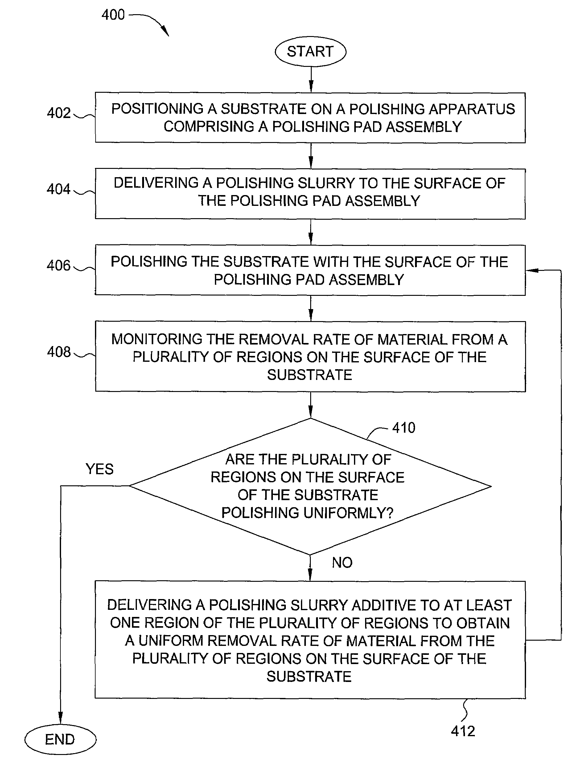
[0020]Embodiments described herein relate to removing material from a substrate. More particularly, the embodiments described herein relate to polishing or planarizing a substrate by a chemical mechanical polishing process. Moving forward to 32 nm node and beyond, the performance of CMP processes, such as defect, dishing and corrosion, shows an increased dependence on the chemical composition of polishing slurry, particularly during the initial and final stages of a polishing process. The concentration of certain additives plays a very important role in controlling defect, dishing, and corrosion. However, in practice, such additives are not adjustable during the polishing process and the concentration of such additives varies from the wafer center to wafer edge locations as such additives are not consumed uniformly. In addition, for certain applications inhibitors provided at low concentrations are needed during either the initial stages or final stages of the polishing process. Emb...


PUM

PropertyMeasurementUnit
flow rateaaaaaaaaaa
semiconductoraaaaaaaaaa
flow rateaaaaaaaaaa

Abstract

A method and apparatus for polishing or planarizing a substrate by a chemical mechanical polishing process. In one embodiment a method of processing a semiconductor substrate is provided. The method comprises positioning a substrate on a polishing apparatus comprising a polishing pad assembly, delivering a polishing slurry to a surface of the polishing pad assembly, polishing the substrate with the surface of the polishing pad assembly, monitoring the removal rate of material from a plurality of regions on the surface of the substrate, determining whether the plurality of regions on the surface of the substrate are polishing uniformly, and selectively delivering a polishing slurry additive to at least one region of the plurality of regions to obtain a uniform removal rate of material from the plurality of regions on the surface of the substrate, wherein the removal rate of material from the at least one region is different than at least one other region of the plurality of regions.

Description

BACKGROUND OF THE INVENTION[0001]1. Field of the Invention[0002]Embodiments described herein relate to removing material from a substrate. More particularly, the embodiments described herein relate to polishing or planarizing a substrate by a chemical mechanical polishing process.[0003]2. Description of the Related Art[0004]Sub-quarter micron multi-level metallization is one of the key technologies for the next generation of ultra large-scale integration (ULSI). The multilevel interconnects that lie at the heart of this technology require planarization of interconnect features formed in high aspect ratio apertures, including contacts, vias, trenches and other features. Reliable formation of these interconnect features is very important to the success of ULSI and to the continued effort to increase circuit density and quality on individual substrates and die.[0005]Multilevel interconnects are formed using sequential material deposition and material removal techniques on a substrate s...

Claims


Application Information

Patent Timeline
Patent Type & Authority Patents(United States)
IPC IPC(8): B24B49/00
CPCB24B37/04B24B57/02
Inventor TU, WEN-CHIANGWANG, YOUWANG, YUCHUNKARUPPIAH, LAKSHMANAN
Owner APPLIED MATERIALS INC
Why Eureka
Try Eureka