Slip-fit clamping system for mounting a fitting on a wall

a technology of clamping system and clamping pipe, which is applied in the field of clamping system, can solve the problems of affecting the aesthetics of the rear, affecting the use of water pipes, and requiring a relatively expensive clamping part to be produced, so as to reduce the risk of corrosion, reduce the risk of damage to the gripped pipe, and easy to remove

Active Publication Date: 2012-07-10
KOHLER CO
View PDF52 Cites 7 Cited by
  • Summary
  • Abstract
  • Description
  • Claims
  • Application Information

AI Technical Summary

Benefits of technology

[0011]The fitting further includes a clamp structure having at least two separate clamp parts. The clamp structure is configured so as to be positionable around the member between the member and fitting body when the member is inserted in the cavity. A hole, in which a screw is located, extends radially from the cavity through a wall of the fitting body. If an end of the member is positioned in the cavity, then the screw can be extended radially inward to drive against a first of the separate clamp parts. This causes that clamp part to help retain the end of the member in the cavity.
[0029]The clamp parts are inexpensive to produce and can be installed and used in an intuitive manner. Thus, a reliable system can be provided at acceptable cost.

Problems solved by technology

For example, driving a set screw through the spout directly against the supply pipe (see e.g. U.S. Pat. No. 6,301,727) can provide a secure connection but may weaken a portion of the supply pipe if not done carefully to avoid overtightening.
However, this disrupts the rear aesthetics of the spout to accommodate the bulky clamp mechanism and side wall screw, and requires a relatively costly clamping part to be produced.

Method used


Image

  • Slip-fit clamping system for mounting a fitting on a wall
  • Slip-fit clamping system for mounting a fitting on a wall
  • Slip-fit clamping system for mounting a fitting on a wall

Examples


Embodiment Construction

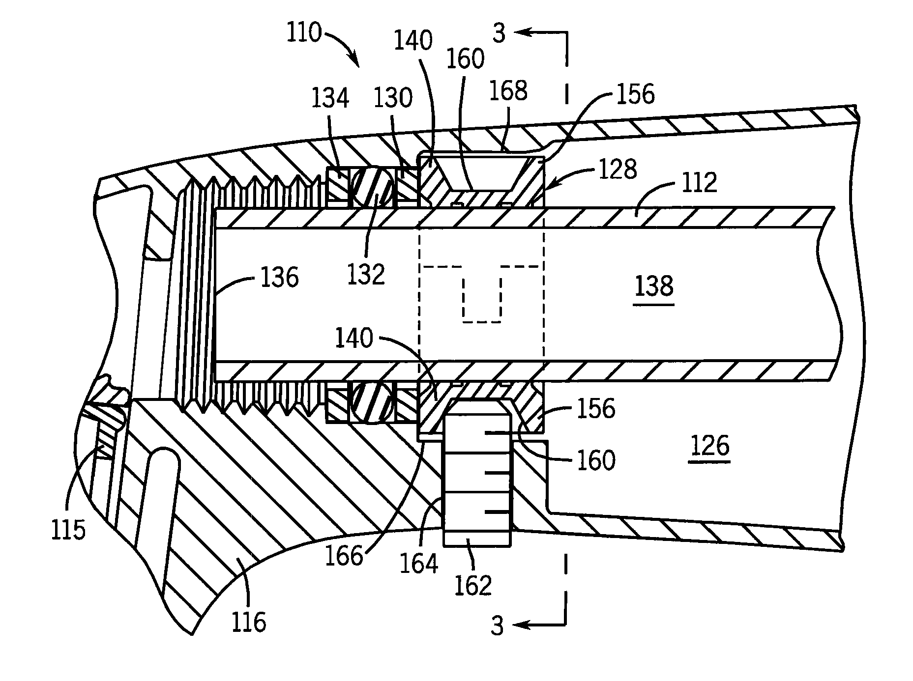
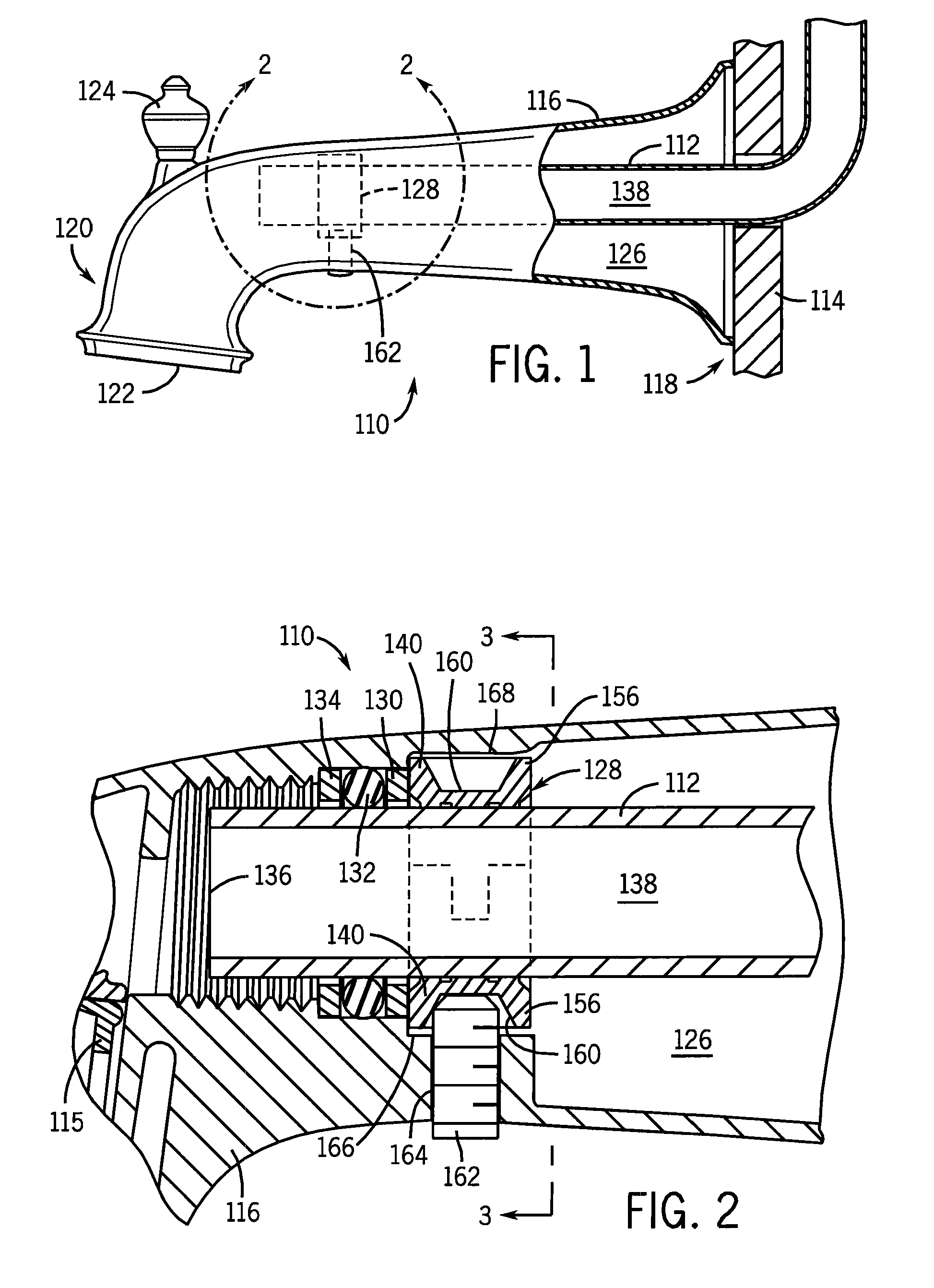
[0041]Referring first to FIGS. 1-3, a bathtub spout 110 is shown attached to a water pipe 112 that extends essentially horizontally through an essentially vertical wall 114. The bathtub spout 110 has a main spout body 116 extending from a rear end 118 that is flush with an outer surface of the room wall 114 to a front end 120 that has a downward extending frontal outlet 122.

[0042]Proximate the frontal outlet 122, a diverter control 124 controls a valve 115 located in the spout body 116. The diverter control 124 can be used in a conventional manner to restrict the flow of water through the frontal outlet 122 when it is desired for the flow to instead be diverted away from the frontal outlet 122 and to, for example, a showerhead (not shown). As is well known, when such a diverter control 124 is in the down position the valve is open and any water from the water pipe is directed to the frontal outlet 122 (and thus typically to a tub below it). If instead the diverter control 124 is pul...


PUM


Abstract

Disclosed are fittings (e.g. tub spouts) suitable for mounting to a member (e.g. a water pipe). Special clamping structures are provided and located in a cavity of a fitting body. The clamping structures have at least two separate clamp parts that surround the water pipe or other member. A set screw can be extended radially inward from a hole in the fitting body to drive a clamp part. This helps to retain the end of the member in the cavity, while distributing clamping load away from a single point.

Description

CROSS-REFERENCE TO RELATED APPLICATION[0001]Not applicable.STATEMENT OF FEDERALLY SPONSORED RESEARCH OR DEVELOPMENT[0002]Not applicable.BACKGROUND OF THE INVENTION[0003]This invention relates to bath spouts, hand shower holders, shower arms for supporting shower heads, and other wall mountable fittings used in bathrooms and the like. More particularly it relates to clamping systems to mount such items onto their supports.[0004]In the installation of plumbing fittings such as tub spouts it is often necessary to attach the fitting to a water supply pipe or the like that extends essentially horizontally through the wall. In connection with typical installations the spout is slid over the end of the water pipe until a rearward end of the spout is positioned flush with an outer surface of the room wall. Then, the spout is fixed in place using varied means. See e.g. U.S. Pat. No. 2,997,058 (set screw driving a cylindrical intermediary member), U.S. Pat. No. 3,656,503 (threaded connection ...

Claims


Application Information

Patent Timeline
Patent Type & Authority Patents(United States)
IPC IPC(8): E03C1/04
CPCE03C1/042Y10T137/698
Inventor FURSETH, MICHAEL R.
Owner KOHLER CO
Why Eureka
Try Eureka