Floor tool

a technology for floor tools and pivot points, which is applied in the direction of suction nozzles, cleaning equipments, suction cleaners, etc., can solve the problems of more skipping, complicated and therefore expensive pivot points, etc., and achieve the effect of the pivot point of the floor tool, reducing skipping, and increasing the distance between the articulation axis

Active Publication Date: 2012-07-10
DYSON TECH LTD
View PDF11 Cites 16 Cited by
  • Summary
  • Abstract
  • Description
  • Claims
  • Application Information

AI Technical Summary

Benefits of technology

[0016]In the present invention the pivot point about which the floor tool may pivot and thus “skip” against a floor surface is a rear edge of the portion and / or the rearward floor contacting edge of the sole plate. The present invention is advantageous because it extends the distance between the articulation axis and the pivot point of the floor tool. Increasing the distance between the articulation axis and the pivot point by extending at least a portion of the floor engaging surface of the sole plate beyond the back sole plate engaging edge of the head has been found to make it much harder to pivot the floor tool during normal use thus helping to reduce skipping.
[0017]In a preferred embodiment the portion extends beyond the back sole plate engaging edge of the head along the entire or substantially the entire length of the soleplate. In this embodiment the portion is essentially an extension of the floor engaging surface 36 of the sole plate, such that the rearward floor contacting edge is located beyond the back sole plate engaging edge of the head. In this embodiment the pivot point is the rearward floor contacting edge of the sole plate. The portion may be of any suitable length or shape as long as it extends beyond the back sole plate engaging edge of the head to increase the length of the floor engaging surface and thus increase the distance between the articulation axis and the pivot pint.
[0026]In a preferred embodiment the rear lip or one or more sections of the rear lip may curve upwardly, for example upwardly and away from the rear floor contacting edge of the soleplate. It is also possible that at least a section of the rear lip may be larger than at least another section of the rear lip and / or a section of the front lip. For example, in an embodiment where the portion is an extension of the floor engaging surface of the sole plate i.e. where the floor engaging surface of the sole plate extends beyond the back sole plate engaging edge of the head, a relatively larger rear lip may extend from the rearward floor contacting edge of the soleplate and a relatively smaller lip may extend from the forward floor contacting edge of the soleplate. Such lips may help to prevent the sole plate “digging in” to a carpet during use of the cleaning appliance.

Problems solved by technology

Although agitation is desirable in most instances, a problem can arise with such floor tools, namely that as the floor tool is pulled backwards along a floor surface the rearward floor contacting edge of the sole plate can act as a pivot point against the floor.
This problem can be more apparent on long pile carpets because as the floor tool starts to pivot about the pivot point the rearward floor contacting edge of the sole plate can dig into the carpet pile causing more skipping.
In order to operate effectively, the above arrangements all require complicated and therefore expensive pivot point arrangements.

Method used


Image

  • Floor tool
  • Floor tool
  • Floor tool

Examples


first embodiment

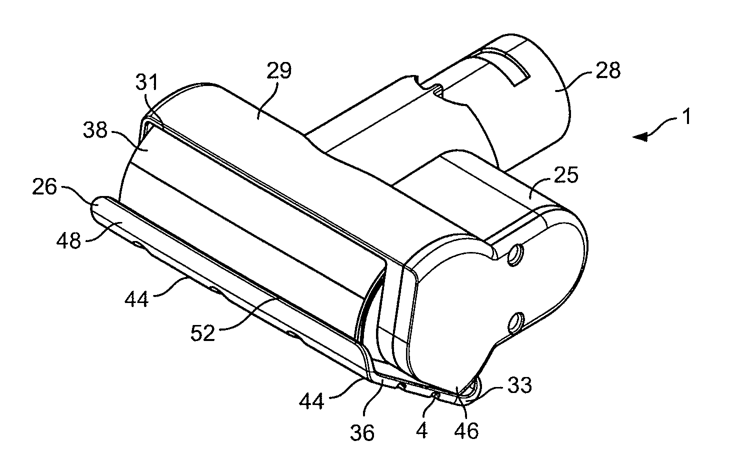
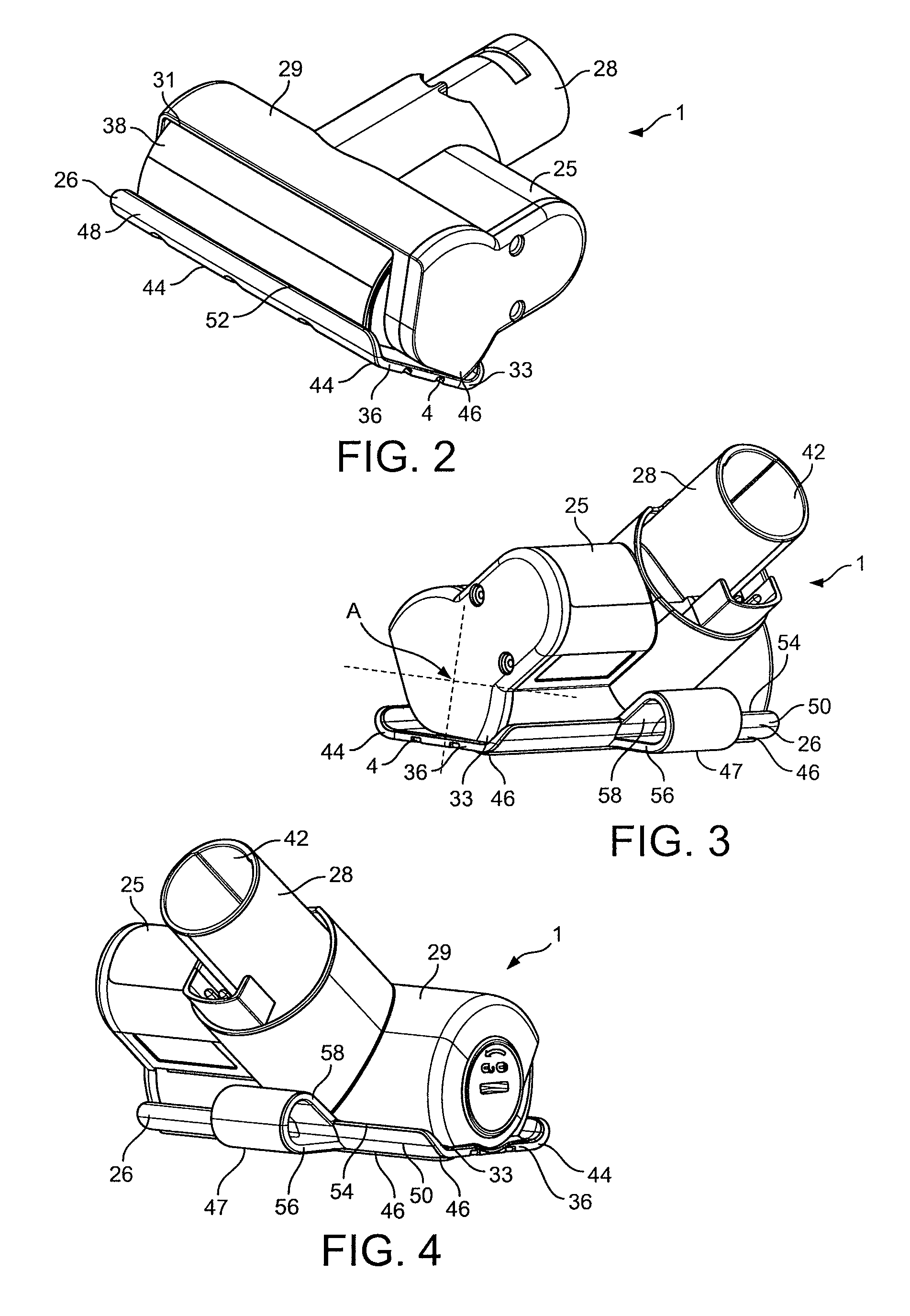
[0047]FIGS. 2 to 7 show the floor tool 1 in greater detail. It can be seen that the floor tool 1 includes a head 25, a sole plate 26 and a connecting arm 28. The connecting arm 28 is rigidly attached to the head 25, although it is possible that it could be pivotally connected to the head 25 if desired. The sole plate 26 is pivotally connected to the head 25 about an articulation axis A (shown in FIGS. 3 and 6).

[0048]The head 25 includes a barrel shaped body 29 in which a brush bar 30 is located. The brush bar 30 is rotatable about the same axis A that the sole plate 26 is rotatable about. The brush bar 30 may be of any suitable construction and may be either motor or turbine driven.

[0049]The soleplate 26 faces a floor surface in use and includes a suction opening 4. The suction opening 4 is in the form of a plurality of apertures 34 defined by a floor engaging surface 36 of the sole plate 26. It can also be seen that the sole plate 26 further comprises upstanding front and rear wall...

third embodiment

[0056]In the third embodiment shown in FIGS. 11 to 13 the portion 56 is an extension of the floor engaging surface 36 of the soleplate 26 along its entire length. Again this portion extends rearwardly in the same plane as the floor contacting surface 36 of the sole plate 26 for a distance beyond the back sole plate engaging edge 33 of the head 25 and then a rear lip 50 curves upwardly.

[0057]In FIGS. 11 to 13 it can be seen that the rear lip 50 is larger than the front lip 48. In an alternative embodiment the rear lip 50 may be the same size or smaller than the front lip 48. In another alternative embodiment there may only be one lip 48, 50 or no lips. Again the exact shape of the portion 56 is not important, the important feature is that the distance between the pivot point 47 of the floor tool 1 and the axis A is as large as possible. In this embodiment the pivot point 47 is also the rearward floor contacting edge 46 of the sole plate 26.


PUM


Abstract

The present invention relates to a floor tool for a surface treating appliance including, a sole plate comprising a floor engaging surface having forward and rearward floor contacting edges and a suction opening, a head which is pivotable relative to the sole plate about an articulation axis between forward and rearward positions, the head having a front sole plate engaging edge and a back sole plate engaging edge, and a connecting arm comprising an outlet in communication with the suction opening, at least a portion of the floor engaging surface of the sole plate extends beyond the back sole plate engaging edge of the head when the head is in the rearward position.

Description

REFERENCE TO RELATED APPLICATIONS[0001]This application claims priority of United Kingdom Application No. 0903588.2 filed Mar. 3, 2009, the entire contents of which are incorporated herein by reference.FIELD OF THE INVENTION[0002]This invention relates to a floor tool for a surface treating appliance. Particularly, but not exclusively, the invention relates to a floor tool for a vacuum cleaner.BACKGROUND OF THE INVENTION[0003]A wide range of vacuum cleaners are available on the market and include upright cleaners, stick vac cleaners, cylinder cleaners and hand-held cleaners. A cylinder vacuum cleaner normally has a main body containing a motor and fan assembly for drawing an airflow into the main body and separating apparatus for separating dirt and dust from the airflow. The separating apparatus may take the form of, for example, a cyclonic separator, a bag or a filter. A hose and wand assembly is connected to the main body and a floor tool is attached to the end of the wand remote...

Claims


Application Information

Patent Timeline
Patent Type & Authority Patents(United States)
IPC IPC(8): A47L9/02
CPCA47L9/0477A47L9/0666A47L5/26A47L9/02A47L5/24A47L5/36A47L9/04A47L11/02A47L11/38A47L11/40
Inventor KNOX, ALEXANDER STUARTREN, TAN YEOUBONG, SAI HER
Owner DYSON TECH LTD
Why Eureka
Try Eureka