Structural assembly with a tied, flexurally deformed panel

a technology of flexural deformation and structural assembly, which is applied in the direction of advertising, decoration, and application, can solve the problems of corrugated repose and reduction of any tension in the plane element, and achieve the effects of high coefficient of restitution, high load-bearing capability, and high in-plane tensile strength

Inactive Publication Date: 2012-07-10
CONTRA VISION
View PDF52 Cites 21 Cited by
  • Summary
  • Abstract
  • Description
  • Claims
  • Application Information

AI Technical Summary

Benefits of technology

[0032]Such structural assemblies may be referred to as “tied, flexurally deformed panel” or “tied, flexed panel” structures. A principal advantage of the invention is that the structural assembly is typically fabricated from planar and optionally linear components which can be easily manufactured and subsequently processed, for example printed with a design. The components can be packaged flat or rolled, and can be transported more easily and economically than 3 dimensional structural members that are pre-formed (for example cast concrete structures or conventional steelwork structural members) and can be assembled temporarily semi-permanently or permanently at sites remote from the component manufacturing site or sites. Temporary or semi-permanent embodiments of the invention can be designed to be easily dismantled and re-used or be conveniently transported to recycling or waste disposal centers.
[0033]The flexed panel or panels and tensioned membrane tie or tie members combine to provide a structural assembly that is typically more stable and has more load-bearing capability than the individual members or the same elements combined in their non-flexed or non-tensioned state.
[0034]Panels are typically plane before being flexed and typically have sufficiently high in-plane tensile strength so as not to accommodate double curvature. However, a variety of geometric shapes can be achieved by single curvature of plane panels, for example a variety of single curves or repetitive or varied wave shapes can be achieved, as well as a variety of “shell” structures.
[0035]Transparent panels and tie membranes are used, for example, to make transparent or partially transparent display assemblies with no independent framing or other such obstruction to through vision. Such assembles are, in particular, suited to support or comprise one-way vision or other see-through vision control panels, for example as disclosed in US RE37,186 or U.S. Pat. No. 6,212,805. Optionally, the linear connector or connectors are also transparent, for example comprising transparent gluelines or transparent profiled sections, for example of clear, extruded polycarbonate.
[0036]Assemblies of the invention are optionally designed to be of variable geometry, typically by enabling the tie member or members to be altered in length, for example by means of tie rods that can be varied in length, for example by means of a turnbuckle, or wound elastic tie members that can be further wound or un-wound. The capability to amend the geometry of an assembly has many potential benefits, for example from minor adjustments to accommodate tolerances or errors in building construction, to substantial changes in geometry, for example to amend the effective area of a tied, flexed panel, for example acting as a sail on a boat or wind-powered electricity generating device.
[0037]Assemblies of the invention are optionally extremely flexible, to allow substantial deflection under load, such deflection being reversible if both the panel and tie elements are not loaded beyond their short-term elastic range. In structural engineering terms, assemblies of the invention typically have a very high coefficient of restitution after short-term loading, even those incorporating plastic materials. A membrane tie member optionally performs a rebound or trampoline function, taking advantage of the stored energy and elastic deformation capability of a suitably designed assembly of the invention. Such properties are useful in the manufacture of many products, from very small spring assemblies to sprung platforms, for example as may be used in “bouncy castles”. The invention is optionally used to create energy through changing, repeated flexure of a panel and tensile strain of a membrane tie member, for examples if the invention comprises materials which create an electric current upon flexure, for example buoys at sea are capable of being illuminated by wave action upon an assembly of the invention comprising such flexurally activated material.

Problems solved by technology

However, in the case of corrugated paper or card, the corrugated element is typically deformed in a material state and under conditions such that, were it not attached to the one or more planar sheets, it would still be corrugated in repose.
The curved and plane components are connected by means of folded card tabs, which will inevitably open up in use and cause reduction of any tension in the plane element.

Method used


Image

  • Structural assembly with a tied, flexurally deformed panel
  • Structural assembly with a tied, flexurally deformed panel
  • Structural assembly with a tied, flexurally deformed panel

Examples


Embodiment Construction

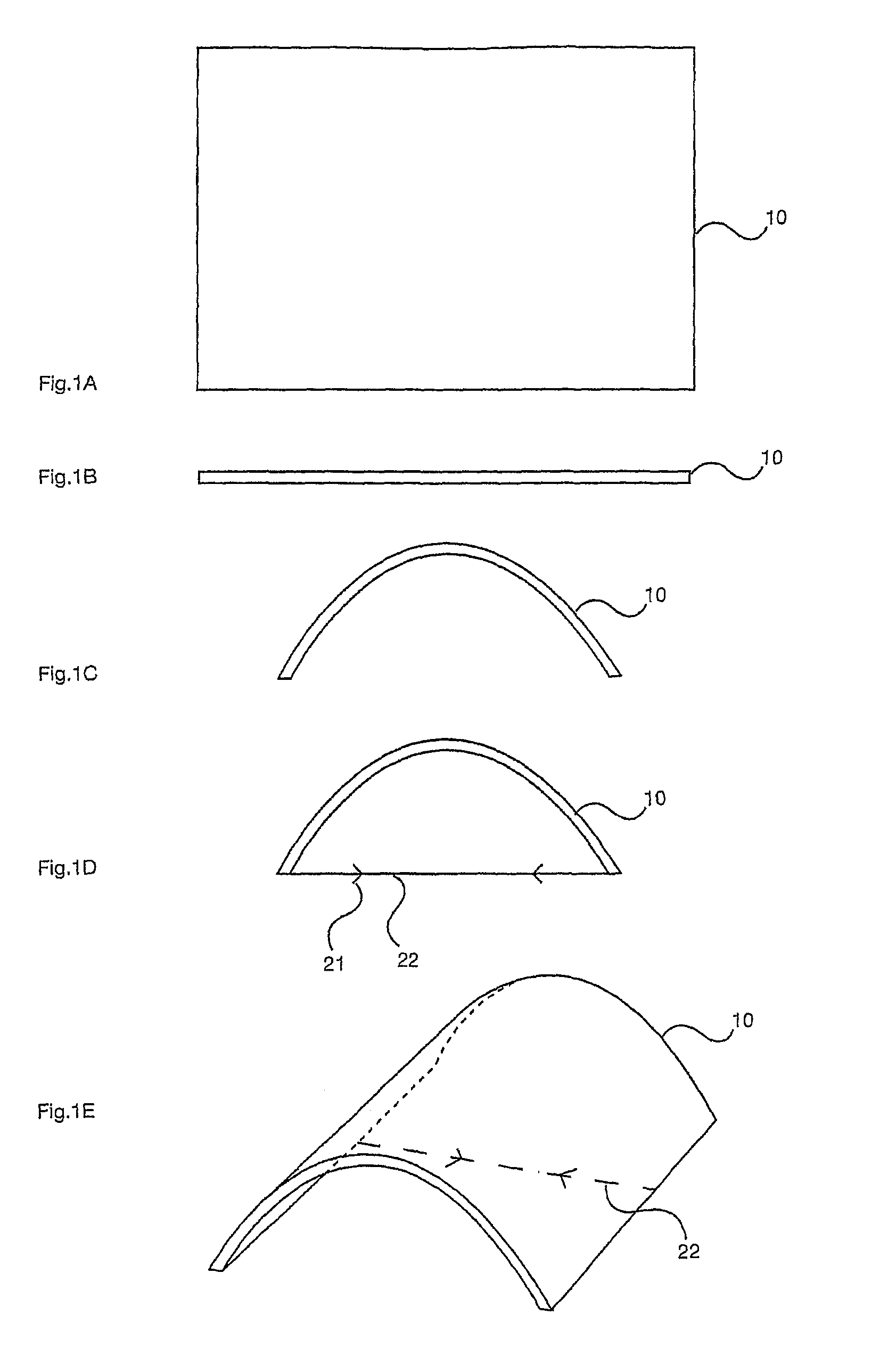
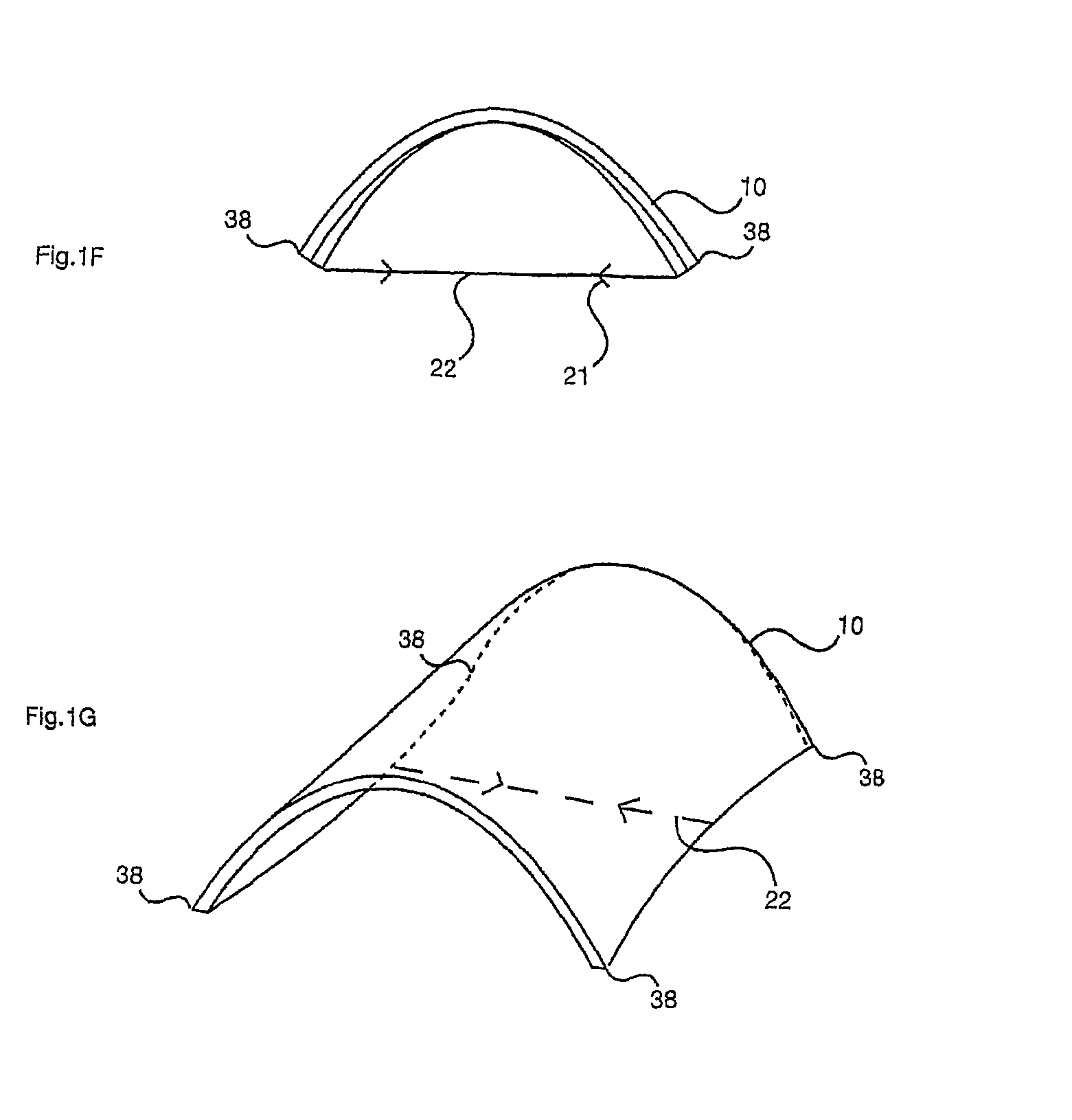
[0270]FIGS. 1A-G illustrate panel 10, tied by a single tie rod 22. Panel 10 is shown on plan in FIG. 1A and in edge elevation in FIG. 1B before flexure, illustrated in FIG. 1C. FIG. 1D illustrates single linear tie rod or cable 22 (the arrow heads 21 indicating tensile force) and a diagrammatic perspective of the resultant temporary assembly is illustrated in FIG. 1E. FIG. 1F illustrates the secondary deflection of the corners of the panel 38 in elevation, which is also shown in perspective in FIG. 1G. Such an assembly may be used temporarily to create an “intermediate panel geometry” before attaching the membrane tie and linear connector or connectors. In the final “flexurally deformed geometry”, this secondary deflection or out-of-alignment is eliminated, a principle advantage of the invention.

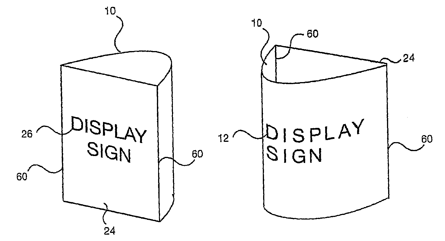
[0271]FIGS. 2A-C are similar to FIGS. 1A-C and FIG. 2D illustrates a flexed, tied panel assembly 20 comprising a membrane tie 24, linear connectors 60 and panel 10, which is deformed into a ...


PUM

PropertyMeasurementUnit
thicknessaaaaaaaaaa
thicknessaaaaaaaaaa
tensile forceaaaaaaaaaa

Abstract

An assembly includes a flexurally deformed panel, which is connected to a membrane tie by a linear connector and is tied by the membrane tie to form a geometrically stable pre-stressed structure. More than one panel may be flexurally deformed and tied together in an assembly and more than one membrane tie may be present within an assembly. Panels are typically semi-rigid sheet materials, for example metal sheets, plastic sheets, or sheets of composite materials, such as glass or carbon fibre reinforced plastics or resins. Membrane tie members are typically flexible, for example plastic films, fabrics or nets or arrays of rods or cables. The assemblies have many different geometric forms and many different practical applications. Assemblies may be relatively large, for example demountable and reusable shelters or flat-pack point-of-purchase display assemblies, or may be relatively small, for example a photograph or postcard display system.

Description

CROSS REFERENCE TO RELATED APPLICATIONS[0001]This is the U.S. National Phase of PCT / IB2006 / 003667, filed Aug. 21, 2006, which in turn claims priority to U.S. provisional application Ser. No. 60 / 709,431, filed Aug. 19, 2005, the contents of both of which are incorporated herein in their entirety by reference.BACKGROUND[0002]1. Field of the Invention[0003]Embodiments of the present invention relate to structural systems or structures comprising a flexurally deformed panel.[0004]2. Description of Related Art[0005]Structural systems involving more than one panel connected together are commonplace, for example folded plate roofs, boxes, etc. Connecting two originally planar elements together, one of which is substantially deformed, is also known. For example, corrugated paper or card comprises a sheet of plane paper or card which is deformed by means of pressure, heat and water content (but not flexural stress) into a corrugated shape, for example of sinusoidal cross-section, and is then...

Claims


Application Information

Patent Timeline
Patent Type & Authority Patents(United States)
IPC IPC(8): G09F17/00G09F15/00
CPCG09F1/06G09F1/10G09F7/18G09F15/0025G09F15/0043G09F15/0068G09F15/0075G09F15/02G09F19/22G09F1/065G09F15/0062Y10T29/49863
Inventor HILL, G. ROLAND
Owner CONTRA VISION
Why Eureka
Try Eureka