[0031]Such structural assemblies may be referred to as “tied, flexurally deformed panel” or “tied, flexed panel” structures. A principal
advantage of the invention is that the structural assembly is typically fabricated from planar and optionally linear components which can be easily manufactured and subsequently processed, for example printed with a design. The components can be packaged flat or rolled, and can be transported more easily and economically than 3 dimensional structural members that are pre-formed (for example cast concrete structures or conventional steelwork structural members) and can be assembled temporarily semi-permanently or permanently at sites remote from the component manufacturing site or sites. Temporary or semi-permanent embodiments of the invention can be designed to be easily dismantled and re-used or be conveniently transported to recycling or
waste disposal centers.
[0032]The flexed panel or panels and tensioned membrane tie or tie members combine to provide a structural assembly that is typically more stable and has more load-bearing capability than the individual members or the same elements combined in their non-flexed or non-tensioned state.
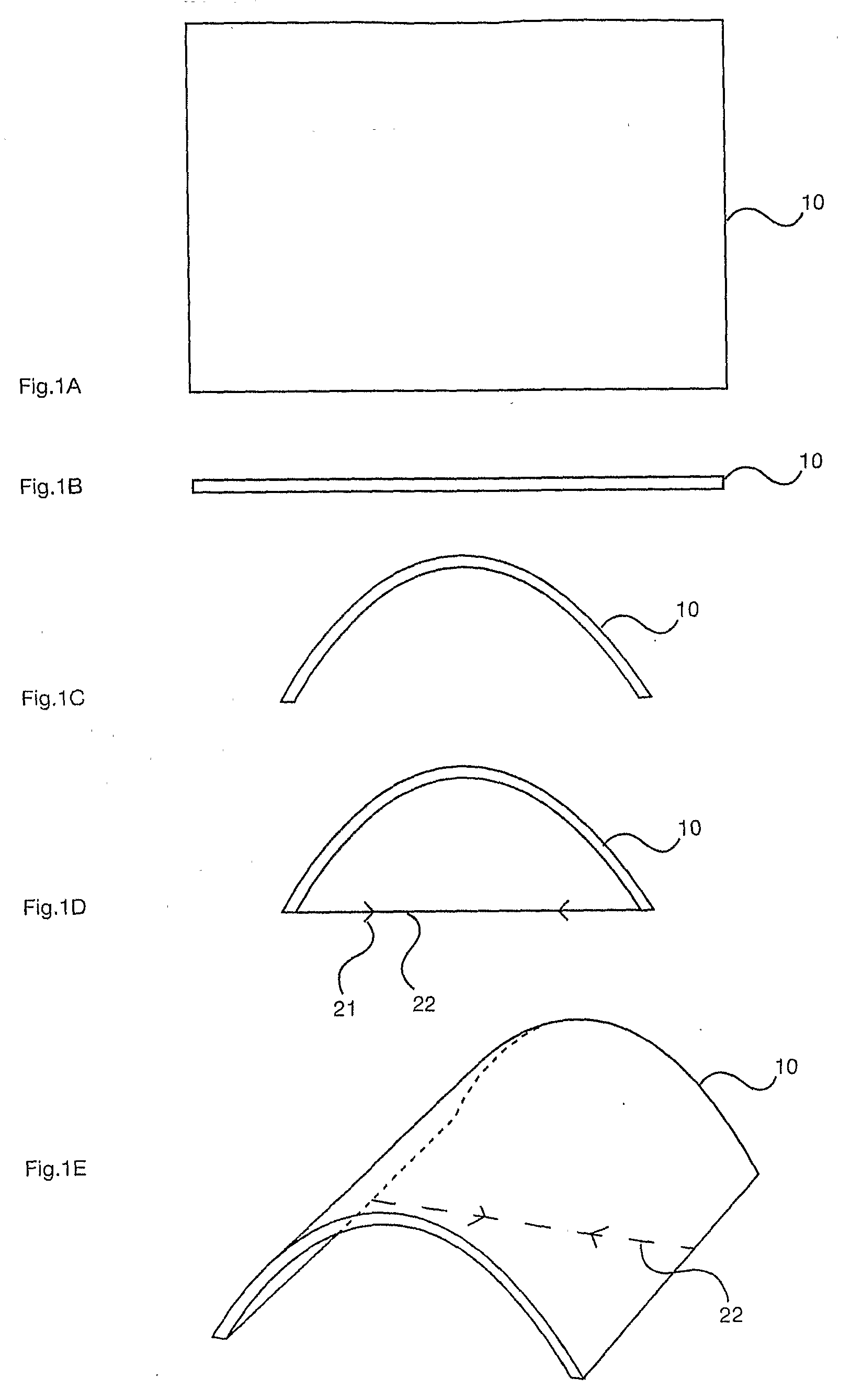
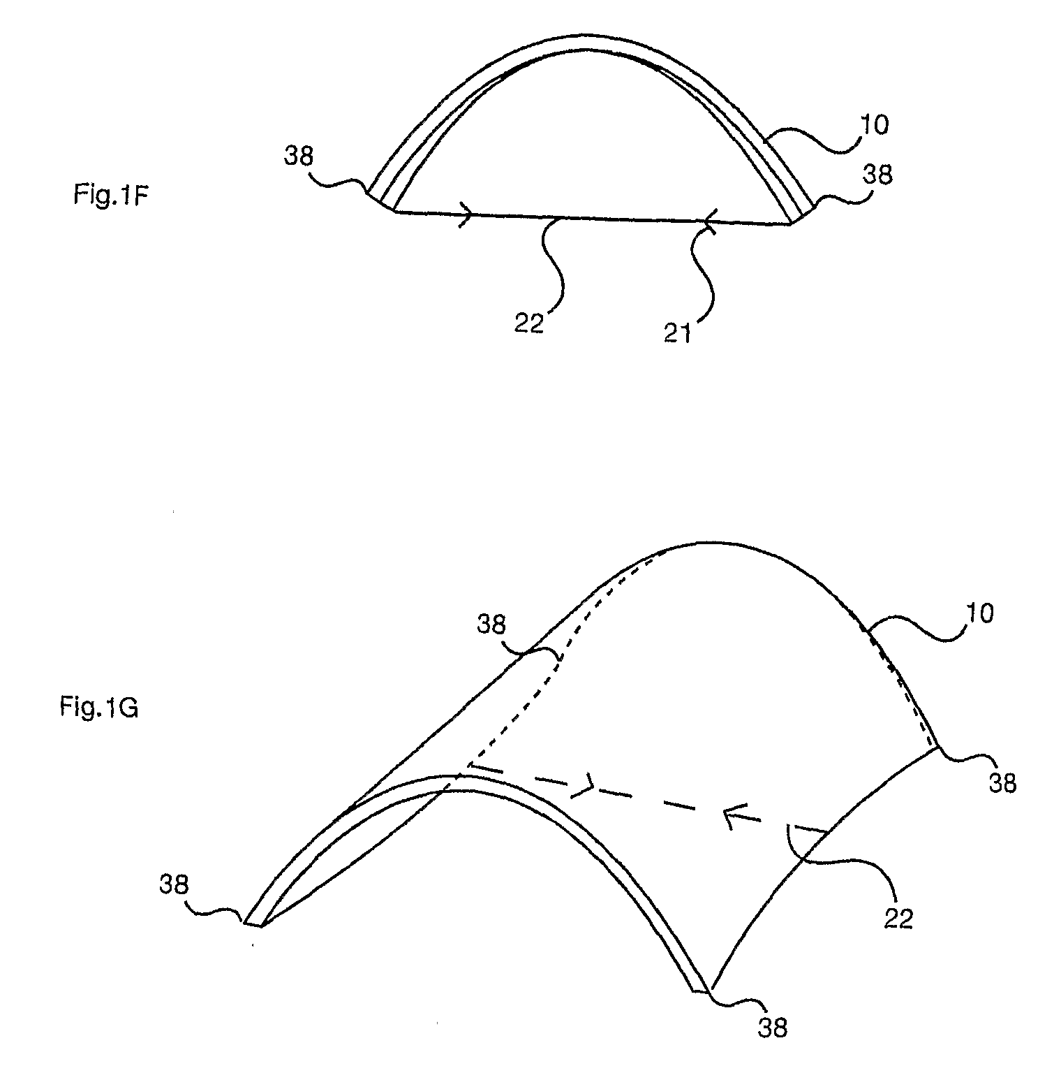
[0033]Panels are typically plane before being flexed and typically have sufficiently high in-plane tensile strength so as not to accommodate
double curvature. However, a variety of geometric shapes can be achieved by single curvature of plane panels, for example a variety of single curves or repetitive or varied wave shapes can be achieved, as well as a variety of “shell” structures.
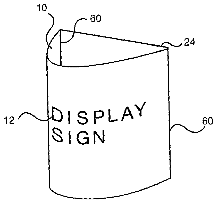
[0034]Transparent panels and tie membranes are used, for example, to make transparent or partially
transparent display assemblies with no independent framing or other such obstruction to through vision. Such assembles are, in particular, suited to support or comprise one-way vision or other see-through
vision control panels, for example as disclosed in US RE37,186 or U.S. Pat. No. 6,212,805. Optionally, the linear connector or connectors are also transparent, for example comprising transparent gluelines or transparent profiled sections, for example of clear, extruded
polycarbonate.
[0035]Assemblies of the invention are optionally designed to be of
variable geometry, typically by enabling the tie member or members to be altered in length, for example by means of tie rods that can be varied in length, for example by means of a turnbuckle, or wound elastic tie members that can be further wound or un-wound. The capability to amend the geometry of an assembly has many potential benefits, for example from minor adjustments to accommodate tolerances or errors in
building construction, to substantial changes in geometry, for example to amend the effective area of a tied, flexed panel, for example acting as a sail on a boat or wind-powered
electricity generating device.
[0036]Assemblies of the invention are optionally extremely flexible, to allow substantial deflection under load, such deflection being reversible if both the panel and tie elements are not loaded beyond their short-term elastic range. In
structural engineering terms, assemblies of the invention typically have a very high
coefficient of restitution after short-term loading, even those incorporating
plastic materials. A membrane tie member optionally performs a rebound or trampoline function, taking
advantage of the
stored energy and elastic deformation capability of a suitably designed assembly of the invention. Such properties are useful in the manufacture of many products, from very small spring assemblies to sprung platforms, for example as may be used in “bouncy castles”. The invention is optionally used to create energy through changing, repeated flexure of a panel and
tensile strain of a membrane tie member, for examples if the invention comprises materials which create an
electric current upon flexure, for example buoys at sea are capable of being illuminated by wave action upon an assembly of the invention comprising such flexurally activated material.

