Shifting control system

a control system and shift control technology, applied in mechanical equipment, gearing details, instruments, etc., can solve the problems of drag torque, difficult to synchronize the forward and reverse rotation of the synchronous meshing mechanism participating in the above-mentioned pre-shifting, and the rotational difference between the input and output of the clutch, so as to prevent combustion damage

Active Publication Date: 2012-07-10
NISSAN MOTOR CO LTD
View PDF9 Cites 12 Cited by
  • Summary
  • Abstract
  • Description
  • Claims
  • Application Information

AI Technical Summary

Benefits of technology

[0008]It has been discovered that in the above technology that pre-shifting of the gear shift stage group for the release-side clutch is allowed unconditionally when the release-side clutch is in a released state. This results in several problems when the engage-side clutch is in a slip engagement state a rotational difference between exists the input and output of the clutch. Specifically, when the clutch is in a released state or a completely engaged state, slippage does not occur, no heat is generated, and there is no need for cooling. However, when slip engagement occurs, a rotational difference exists between the input and output of the clutch. Thus, during slip engagement, cooling of the clutch is necessary in order to prevent combustion damage to the clutch due to heat generation or early degradation due to excessive heating of the operating oil.
[0012]There thus arises the problem that shifting itself that occurs via this pre-shifting becomes difficult or impossible, as well as the problem that the synchronous meshing mechanism is damaged by unnatural and forced synchronous action, reducing durability.

Problems solved by technology

It has been discovered that in the above technology that pre-shifting of the gear shift stage group for the release-side clutch is allowed unconditionally when the release-side clutch is in a released state.
This results in several problems when the engage-side clutch is in a slip engagement state a rotational difference between exists the input and output of the clutch.
However, when slip engagement occurs, a rotational difference exists between the input and output of the clutch.
This can result in drag torque on the pre-shift-side (release-side) clutch being transmitted to the related synchronous meshing mechanism via the introduced lubricating oil.
This clutch drag torque makes it difficult to synchronize the forward and reverse rotation of the synchronous meshing mechanism participating in the aforementioned pre-shifting.
As a result, this pre-shifting becomes difficult or impossible.

Method used


Image

  • Shifting control system
  • Shifting control system
  • Shifting control system

Examples


Embodiment Construction

[0025]Selected embodiments of the present invention will now be explained with reference to the drawings. It will be apparent to those skilled in the art from this disclosure that the following descriptions of the embodiments of the present invention are provided for illustration only and not for the purpose of limiting the invention as defined by the appended claims and their equivalents.

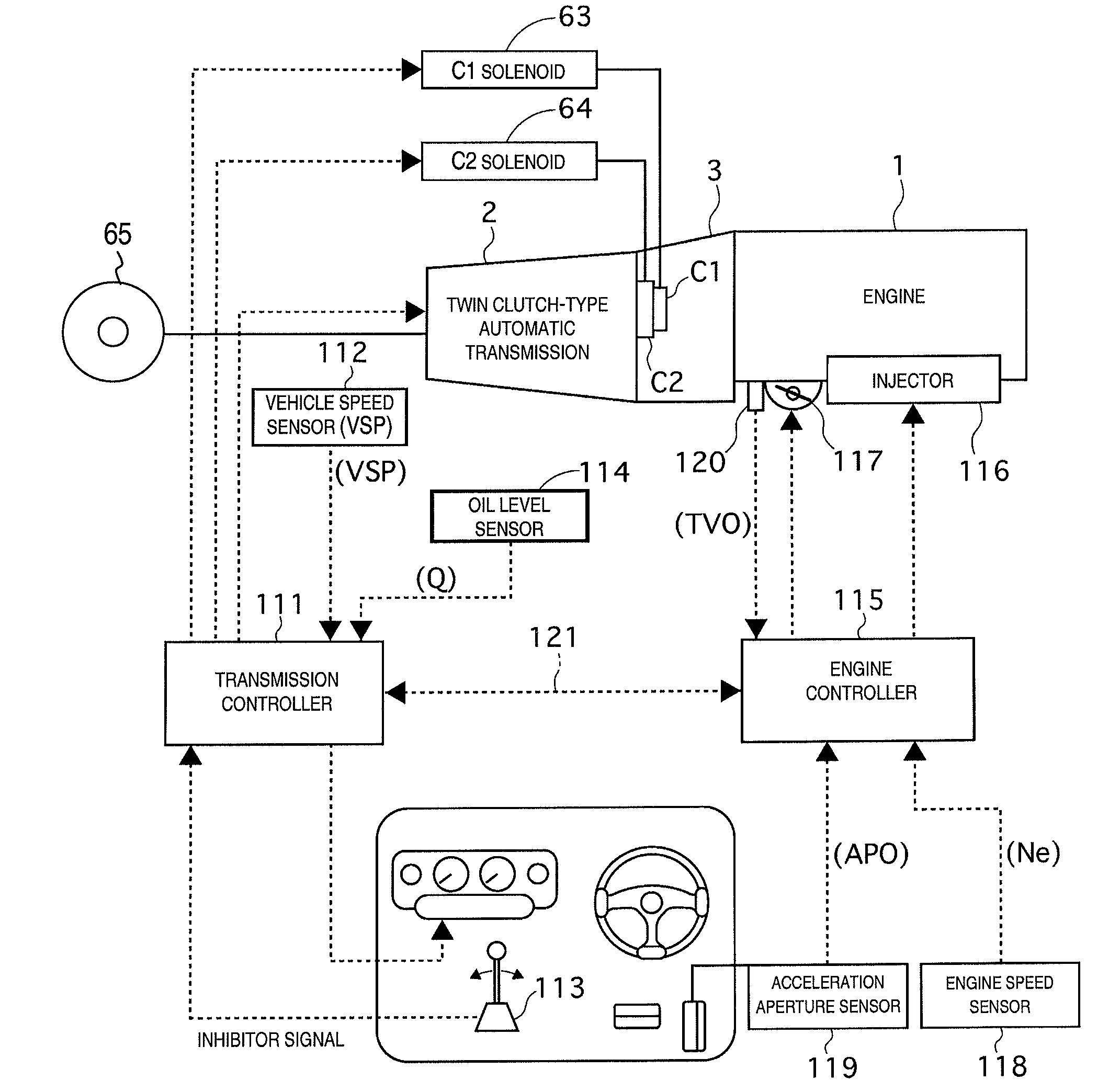
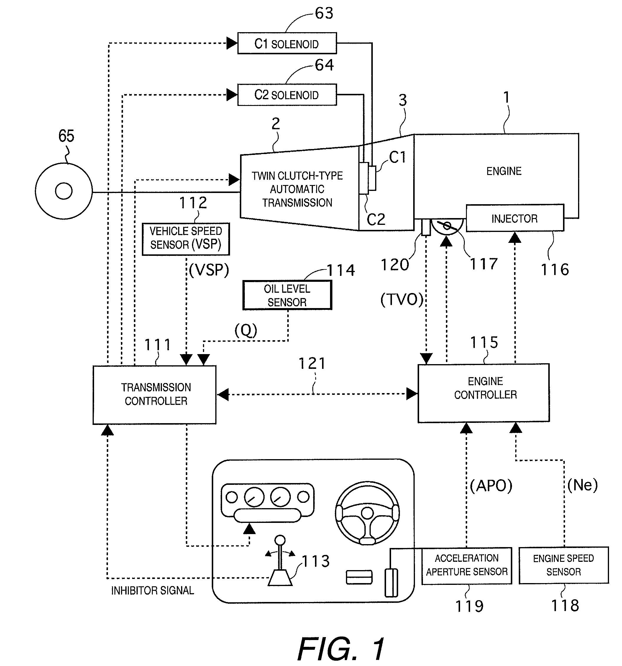
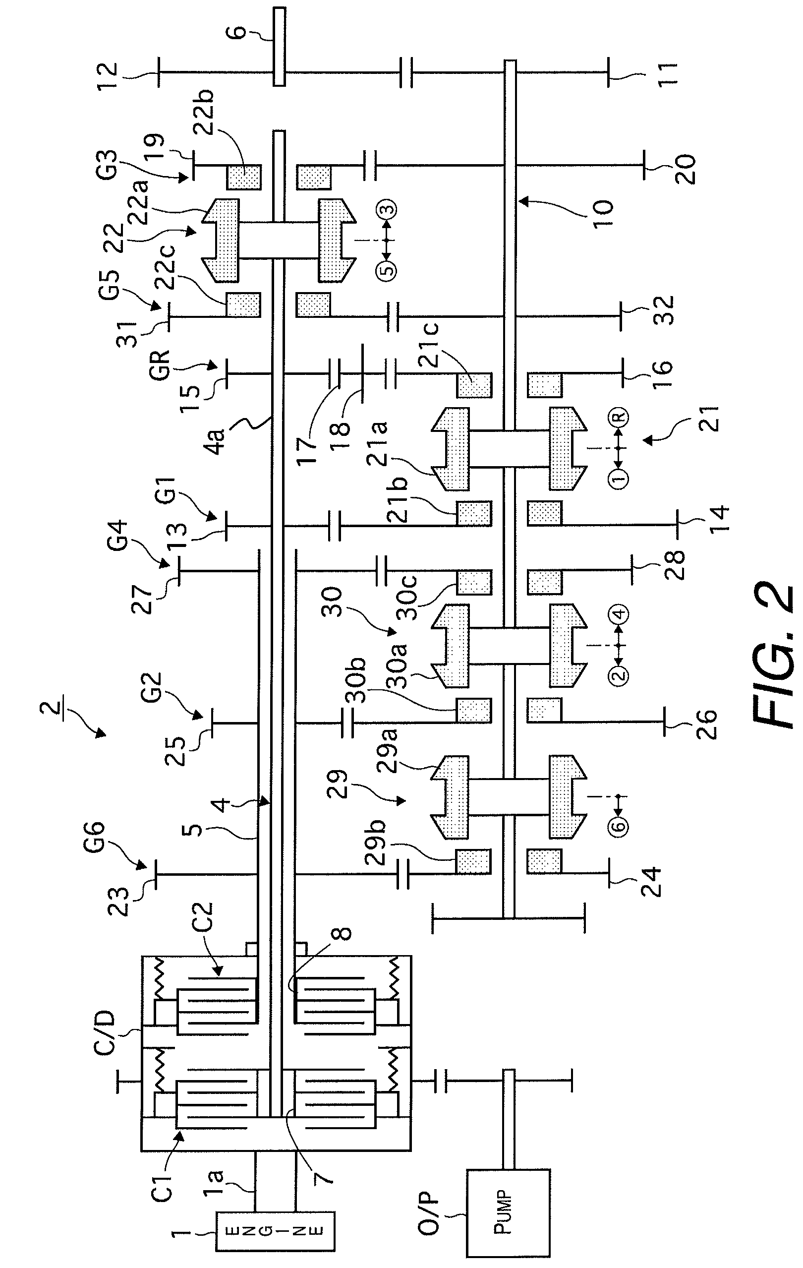
[0026]Referring initially to FIG. 1, a vehicle power train and control system are schematically illustrated in accordance with a first embodiment. The vehicle power train includes an engine 1 and a twin clutch-type automatic transmission 2 that is equipped with the shifting control system. FIG. 2 is a diagram of some main components of the twin clutch-type automatic transmission. As seen in FIG. 2, an output shaft or crankshaft 1a of the engine 1 is selectively linked to a first input shaft 4 and a second input shaft 5 by a pair of automatic wet rotary clutches C1 and C2, respectively. The clutches...


PUM


Abstract

A shifting control system has two gear shift stage groups, two clutches, a clutch release detection section, a pre-shift controller, a clutch oil level detection section and a pre-shift inhibiting section. The clutches are alternately engaged to selectively transmit power from an engine to a wheel. The clutch release detection section detects a release-side clutch which corresponds to the clutch that is in a released state. The pre-shift controller operates a meshing mechanism of the gear shift stage group corresponding to the release-side clutch, so as to undergo pre-shifting when the other clutch is engaged as an engage-side clutch. The clutch oil level detection section determines whether an oil level in the release-side clutch is equal to or greater than a preset oil level. The pre-shift inhibiting section inhibits pre-shifting while the oil level in the release-side clutch is equal to or greater than a preset oil level.

Description

CROSS-REFERENCE TO RELATED APPLICATIONS[0001]This application claims priority to Japanese Patent Application No. 2007-314396 filed on Dec. 5, 2007 and Japanese Patent Application No. 2008-180852 filed on Jul. 11, 2008. The entire disclosures of Japanese Patent Application Nos. 2007-314396 and 2008-180852 are hereby incorporated herein by reference.BACKGROUND OF THE INVENTION[0002]1. Field of the Invention[0003]The present invention generally relates to a shifting control system for a clutch-type automatic transmission, specifically, a twin clutch-type automatic transmission. More specifically, the present invention relates to a technology for appropriately carrying out pre-shifting in which a selective meshing mechanism is made to undergo advance shifting that governs implementation of a gear shift stage in one gear shift stage group, while a gear shift stage in another gear shift stage group is engaged.[0004]2. Background Information[0005]When a manual transmission is to be convert...

Claims


Application Information

Patent Timeline
Patent Type & Authority Patents(United States)
IPC IPC(8): B60W10/02B60W10/10
CPCF16H61/688F16H59/72F16H2059/6807Y10T477/641F16H57/0473Y10T74/1926Y10T74/19251F16H2306/18
Inventor KATAKURA, SHUSAKUFUJIWARA, SADAMU
Owner NISSAN MOTOR CO LTD
Why Eureka
Try Eureka