
Solenoid valve driving circuit

A solenoid valve driving and driving circuit technology, which is applied to valve details, valve devices, electrical components, etc., can solve the problems of solenoid valve coil combustion damage, etc., and achieve the effects of preventing combustion damage, reducing power consumption, and improving stability

Active Publication Date: 2020-07-24
浙江桃园智能科技有限公司
View PDF5 Cites 2 Cited by
  • Summary
  • Abstract
  • Description
  • Claims
  • Application Information

AI Technical Summary

Problems solved by technology

Although the existing technology can effectively drive the solenoid valve, during the use of the solenoid valve, due to the influence of the drive circuit and the characteristics of the solenoid valve coil itself, as the use time increases, the solenoid valve coil is prone to burning damage.

Method used


Image

  • Solenoid valve driving circuit
  • Solenoid valve driving circuit
  • Solenoid valve driving circuit

Examples


Embodiment Construction

[0021] The following are specific embodiments of the present invention and in conjunction with the accompanying drawings, the technical solutions of the present invention are further described, but the present invention is not limited to these embodiments.

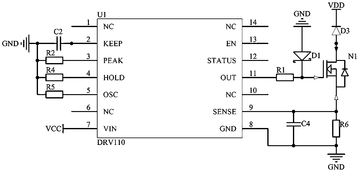
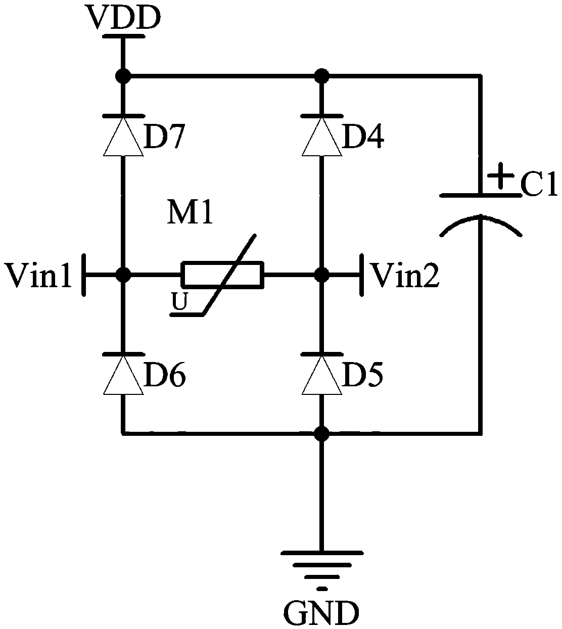
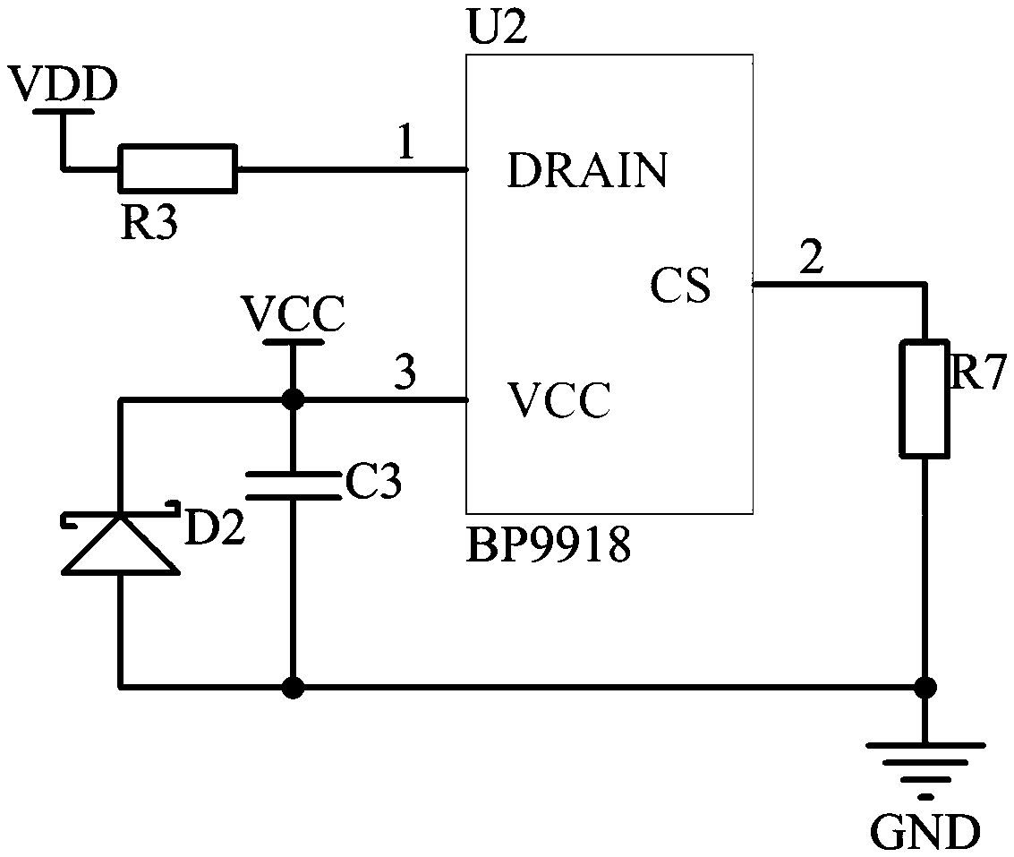
[0022] A solenoid valve driving circuit includes an input rectification and filtering circuit, a power supply circuit, and a control driving circuit. The input rectification filter circuit includes a rectifier bridge and a filter capacitor C1. The rectifier bridge includes four diodes, the cathode of the diode D7 is electrically connected to the cathode of the diode D4, the anode of the diode D7 is electrically connected to the cathode of the diode D6, the cathode of the diode D5 is electrically connected to the anode of the diode D4, and the anode of the diode D5 is electrically connected to the anode of the diode D6 positive electrical connection. The rectifier bridge is also provided with a first power input terminal a...


PUM


Abstract

The invention relates to the technical field of electric circuit driving, in particular to a solenoid valve driving circuit. The circuit comprises an input rectifier filter circuit, a power supply circuit, and a control driving circuit; the input rectifier filter circuit is electrically connected with a power source and outputs filter voltage to the power supply circuit based on voltage of the power source; the power supply circuit outputs power supply voltage to the control driving circuit based on the filter voltage; the control driving circuit is electrically connected with the power supplycircuit and comprises a control chip; and when the control chip receives the power supply voltage, the control chip outputs a broad pulse signal and a narrow pulse signal. According to the prior art,although a solenoid valve can be effectively driven, the solenoid valve is prone to burning out due to the influence of self power consumption of a solenoid valve coil. Compared to the prior art, thesolenoid valve driving circuit meets the need of motivating the solenoid valve by outputting the broad pulse signal and meets the need of continuous operation of the solenoid valve via the narrow pulse signal, so the working current of the solenoid valve is effectively lowered and power consumption of the solenoid valve is thereby lowered.

Description

technical field [0001] The invention relates to the technical field of drive circuits, in particular to a solenoid valve drive circuit. Background technique [0002] With the continuous development of technology, solenoid valves are widely used in different equipment, so how to effectively drive the solenoid valve to work becomes very important. Although the existing technology can effectively drive the solenoid valve, during the use of the solenoid valve, due to the influence of the driving circuit and the characteristics of the solenoid valve coil itself, the solenoid valve coil is prone to burning damage as the use time increases. It can be seen that it is very necessary to design a driving circuit that can make the operation of the solenoid valve coil more stable. Contents of the invention [0003] Aiming at the technical problems of the prior art, the present invention provides a solenoid valve driving circuit. [0004] In order to solve the problems of the technolo...

Claims


Application Information

Patent Timeline
Patent Type & Authority Applications(China)
IPC IPC(8): F16K31/06H02M9/00
CPCF16K31/0675H02M11/00
Inventor 陶国良陶勇
Owner 浙江桃园智能科技有限公司
Learn More