
Atomic clock

a technology of atomic clocks and atomic clocks, which is applied in the field of timekeeping devices, can solve the problems of large size, significant power requirements, and delicate nature of conventional atomic clocks, and achieve the effects of reducing environmental influence on timekeeping, compact, reliable, portable and low-power atomic clocks

Active Publication Date: 2012-07-10
OXFORD UNIV INNOVATION LTD
View PDF5 Cites 21 Cited by
  • Summary
  • Abstract
  • Description
  • Claims
  • Application Information

AI Technical Summary

Benefits of technology

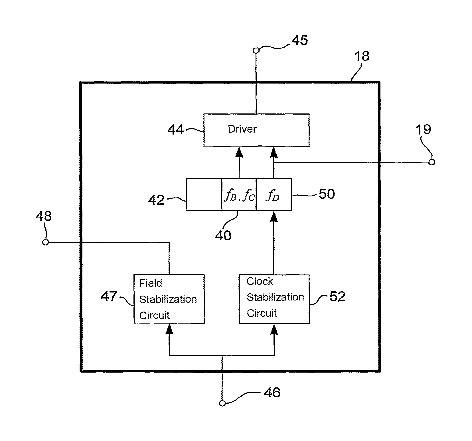
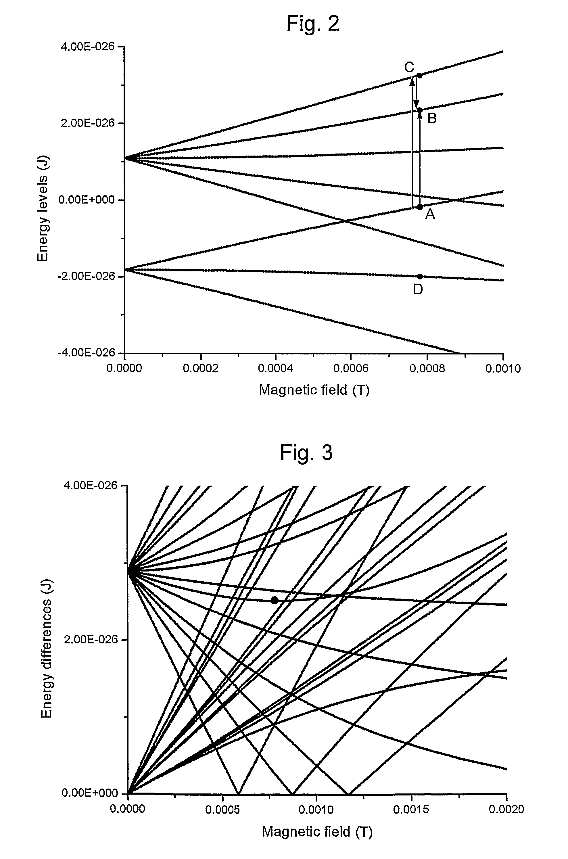
The present invention provides an apparatus for detecting and controlling the response of a system that has at least two states with different energy levels. The system is placed in a medium that includes a magnet device that can adjust the magnetic field. The system is then excited using an excitation device to cause it to transition between the two states. The detection device produces an output that is used to control the magnet device to maintain a zero rate of change in energy difference with changes in magnetic field. This results in the creation of oscillations at a frequency determined by the energy difference between the two states. The technical effect of this invention is the ability to detect and control the response of a system that has at least two states with different energy levels, using a magnet device that can adjust the magnetic field.

Problems solved by technology

Conventional atomic clocks are generally quite large, delicate and have significant power requirements while operating.
Thus there are the problems of providing compact, reliable, portable, low power atomic clocks.
However, there are still problems regarding reducing environmental influence on the time-keeping, especially in portable devices, and also problems with achieving practical measurement and control of such systems.

Method used


Image

  • Atomic clock
  • Atomic clock
  • Atomic clock

Examples


Embodiment Construction

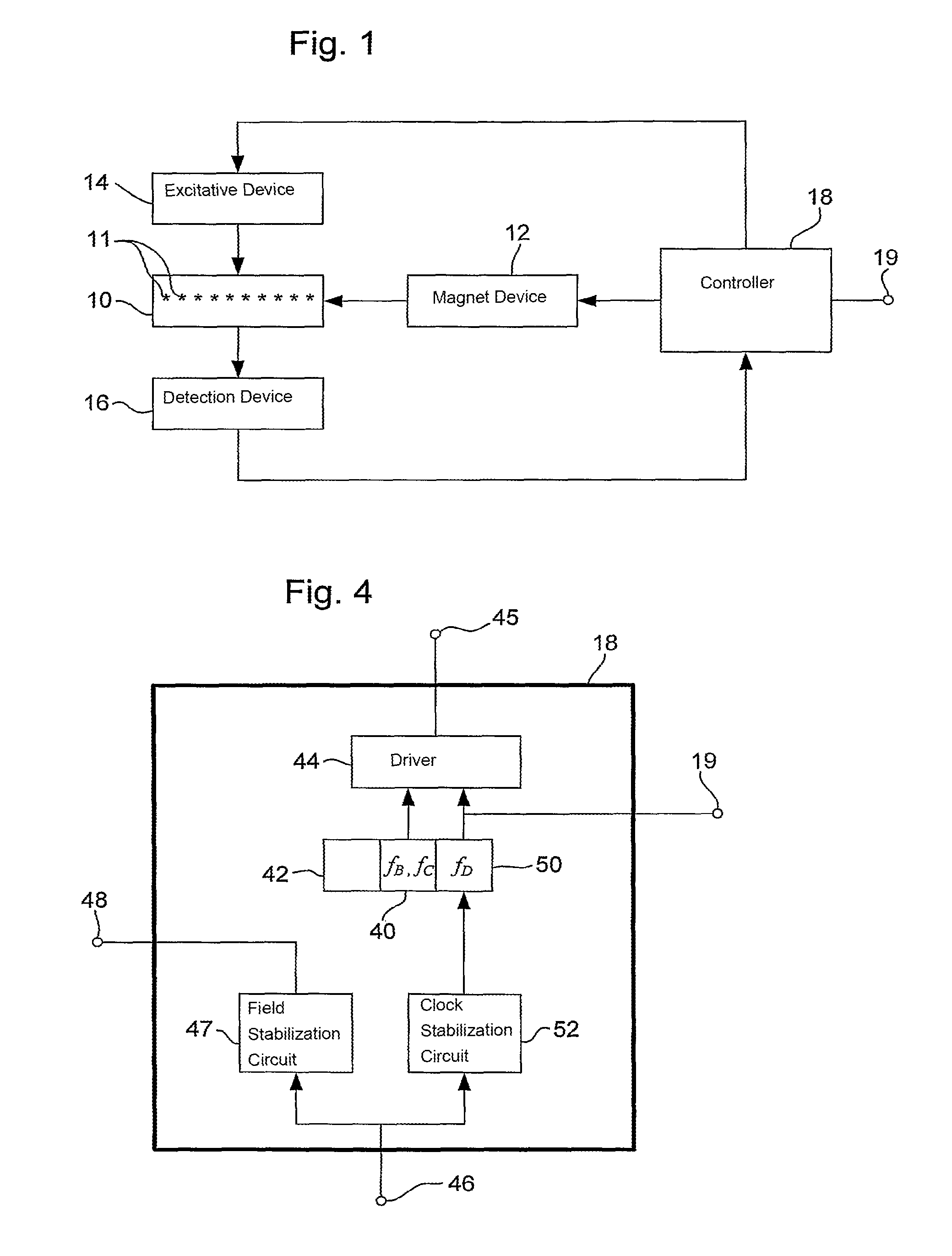
[0018]FIG. 1 shows components of an atomic clock according to an embodiment of the invention. It should, of course, be noted that the term “atomic clock” is simply a convenient shorthand term for such devices. Firstly, they need not necessarily be “clocks”. The heart of the device is an oscillator that can provide oscillations at a stable frequency. For this reasons, such devices may also be known as “frequency standards”. By counting the oscillations of the standard frequency the clock function can be obtained because each oscillation represents a precise period of time. Secondly, the system undergoing the oscillations does not necessarily have to be “atomic” i.e. a single atom or atoms, but could also be ions, atomic clusters, molecular fragments, small molecules or other suitable species. The term “atomic clock” is used herein for convenience and is understood by the person skilled in the art to encompass all of the above terms and further alternatives.

[0019]Referring to FIG. 1, ...


PUM


Abstract

An atomic clock comprises endohedral fullerene systems which provide the standard frequency oscillations. A magnet device applies a magnetic field to the endohedral fullerenes. The applied magnetic field is adjustable. An excitation device both excites each endohedral fullerene system to cause it to undergo transitions which generate the time-keeping oscillations, and also probes the systems such that the oscillations can be measured and the device controlled. A detection device senses the response of the systems induced by the excitation device. The output of the detection device is fed to a controller. The controller produces the atomic clock output, which is the clock signal or frequency standard, and also controls the magnet device and the excitation device. The controller controls the magnetic field applied by the magnet device such that the energy difference of the time-keeping transition is insensitive to variations in magnetic field, thereby stabilizing the frequency of the oscillations and avoiding the effects of changes in external magnetic field.

Description

CROSS-REFERENCE TO RELATED APPLICATIONS[0001]This application claims priority to PCT International Application No. PCT / GB2008 / 002229 filed on Jun. 27, 2008, which claims priority to Great Britain Application No. 0721696.4 filed on Jun. 29, 2007, incorporated by reference herein.FIELD OF THE INVENTION[0002]The present invention relates to the field of time-keeping devices and in particular to the field of devices known as atomic clocks.BACKGROUND OF THE IVNEVTION[0003]Devices called atomic clocks have been known for several decades and are able to keep time with very high precision. Conventional atomic clocks use atoms in a gas phase that can undergo transitions that correspond in energy to electromagnetic radiation in the microwave part of the spectrum. In one example a tunable microwave cavity contains the gas and the cavity can be tuned such that the field in the cavity oscillates very stably at a frequency corresponding to the energy transition in question. The most precise clock...

Claims


Application Information

Patent Timeline
Patent Type & Authority Patents(United States)
IPC IPC(8): H03L7/26
CPCG04F5/14
Inventor BRIGGS, GEORGE ANDREW DAVIDSONARDAVAN, ARZHANG
Owner OXFORD UNIV INNOVATION LTD
Learn More