
Anti-feedback device and anti-feedback method

a technology of anti-feedback device and anti-feedback method, which is applied in the direction of transducer casing/cabinet/support, transducer, etc., can solve the problems of insufficient suppression of feedback, -feedback device utilizing an adaptive filter, and consuming a lot of time before adjusting filter, so as to increase the speed of anti-feedback processing and suppress feedback

Inactive Publication Date: 2012-07-10
YAMAHA CORP
View PDF15 Cites 1 Cited by
  • Summary
  • Abstract
  • Description
  • Claims
  • Application Information

AI Technical Summary

Benefits of technology

The present invention provides an anti-feedback device and method that can suppress feedback and increase the speed of anti-feedback processing. The device includes an anti-feedback filter, a microphone, and a speaker placed in a single acoustic space. An adaptive target signal transfer system is used to select signals from the microphone and output them through the filter. The filter controller controls the filtering characteristic of the anti-feedback filter to suppress peaks in the specific band and estimate the gain of the closed loop outside the specific band. The estimated gain is used to control the amount of suppression of the anti-feedback filter outside the specific band. This reduces the amount of arithmetic computation and speeds up the entire band processing. The anti-feedback method includes steps of selecting signals, down-sampling, filtering, cancelling, updating the filtering coefficient, and controlling the filtering characteristic. The technical effect of the invention is to provide a faster and more effective way to suppress feedback in an acoustic space.

Problems solved by technology

Occurrence of feedback causes problems in many cases in the field of an acoustic feedback system that amplifies a signal of sound collected within single acoustic space by means of a microphone and that emits the thus-amplified signal from a speaker.
However, when a change arises in the state of a transmission system of circulatory sound, the adaptive filter consumes much time before outputting a simulated signal that accurately simulates circulatory sound achieved after occurrence of a change in the state of the transmission system.
For this reason, the anti-feedback device utilizing an adaptive filter encounters a problem of being unable to sufficiently suppress feedback in a situation where an abrupt change arises in the state of the circulatory sound transmission system.
The anti-feedback device utilizing an adaptive filter also encounters a problem of so-called coloration arising when the adaptive filter has insufficient accuracy in estimation of circulatory sound or when a change arises in positional relationship between a speaker and a microphone.
To this end, updating a filtering coefficient requires a large amount of arithmetic calculation, which raises a problem of difficulty in enhancing the speed of anti-feedback processing.

Method used


Image

  • Anti-feedback device and anti-feedback method
  • Anti-feedback device and anti-feedback method
  • Anti-feedback device and anti-feedback method

Examples


first embodiment

[0018]A first embodiment of the present invention is hereunder described by reference to the drawings.

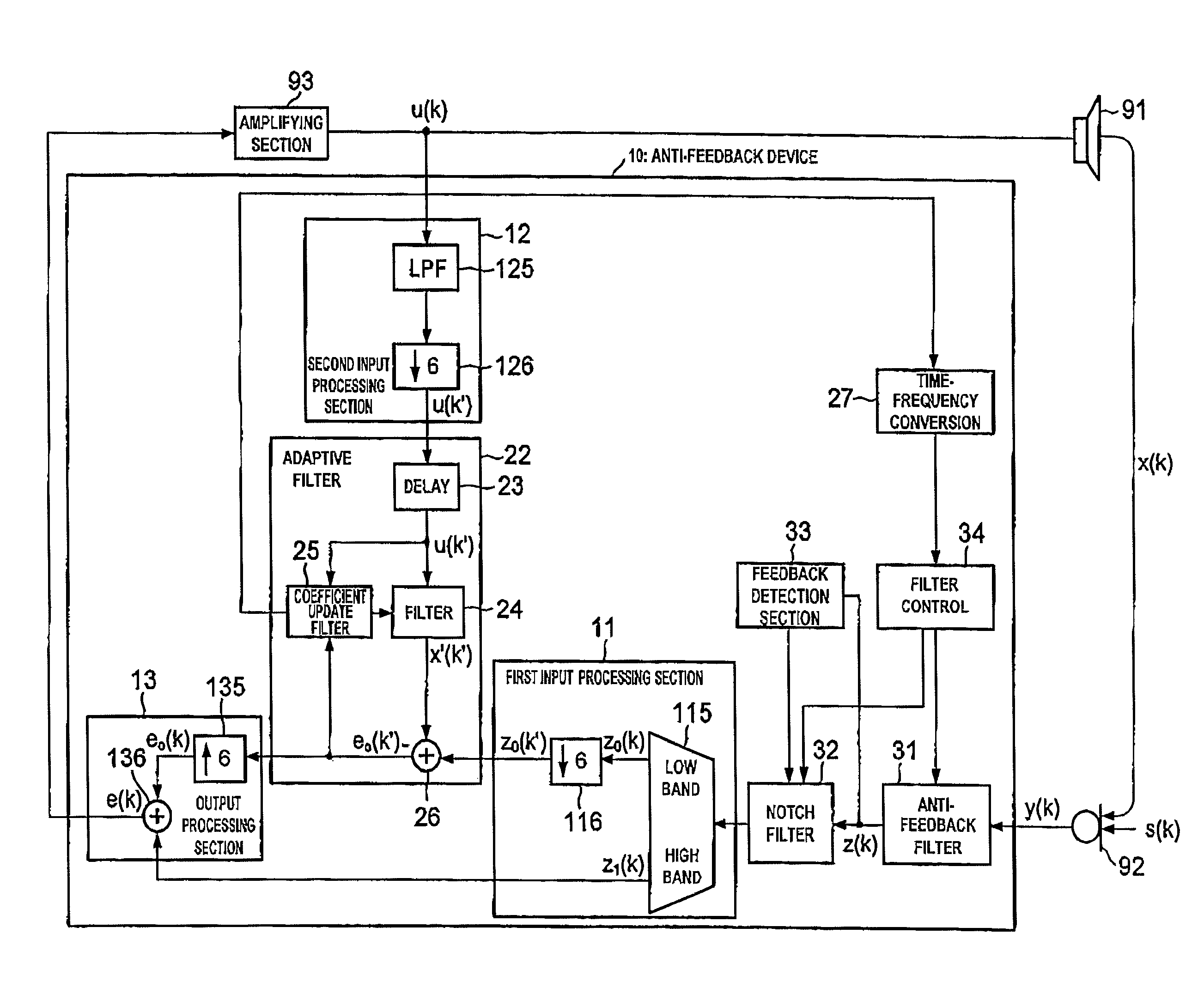
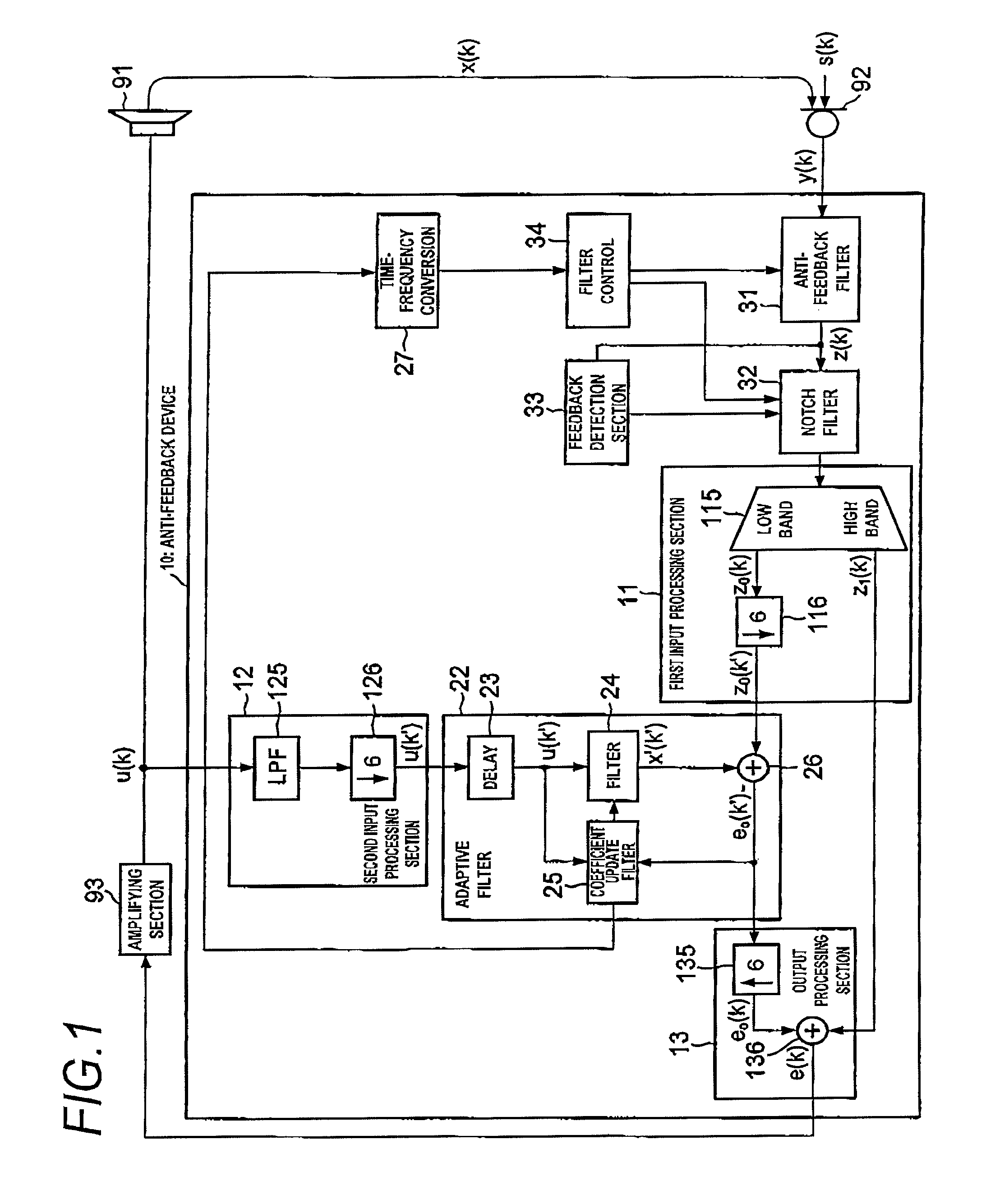
[0019]FIG. 1 shows the configuration of an amplification system including an anti-feedback device 10 of a first embodiment of the present invention. The anti-feedback device 10 is a device that performs the function of suppressing feedback in a closed loop including a speaker 91, a microphone 92, the anti-feedback device 10, and an amplifying section 93 (hereinafter called simply a “closed loop”). The anti-feedback device 10 is interposed between the microphone 92 and the amplifying section 93 of the amplification system that amplifies sound, which has been collected in acoustic space by the microphone 92, through use of the amplifying section 93 and that emits the thus-amplified sound to the acoustic space from the speaker 91. When the microphone 92 and the speaker 91 that emits the sound collected by the microphone 92 are disposed in a single acoustic space, some of the sound emit...

second embodiment

[0038]A second embodiment of the present invention will be hereinbelow described by reference to the drawings.

[0039]According to an aspect of the invention, there is provided an anti-feedback device including: a plurality of anti-feedback filters; a first input processing section that divides the signal output from the adaptive target signal transfer system into a plurality of bands, and that outputs band signals belonging to the divided bands as signals of sampling frequencies suitable for the respective bands; a second input processing section that selects respective band signals belonging to the plurality of bands from a signal input to the adaptive target signal transfer system and that outputs selected band signals as signals of sampling frequencies suitable for the respective bands; a plurality of adaptive filters that correspond to the plurality of respective bands, wherein each adaptive filter subjects the corresponding band signal output from the second input processing sec...


PUM


Abstract

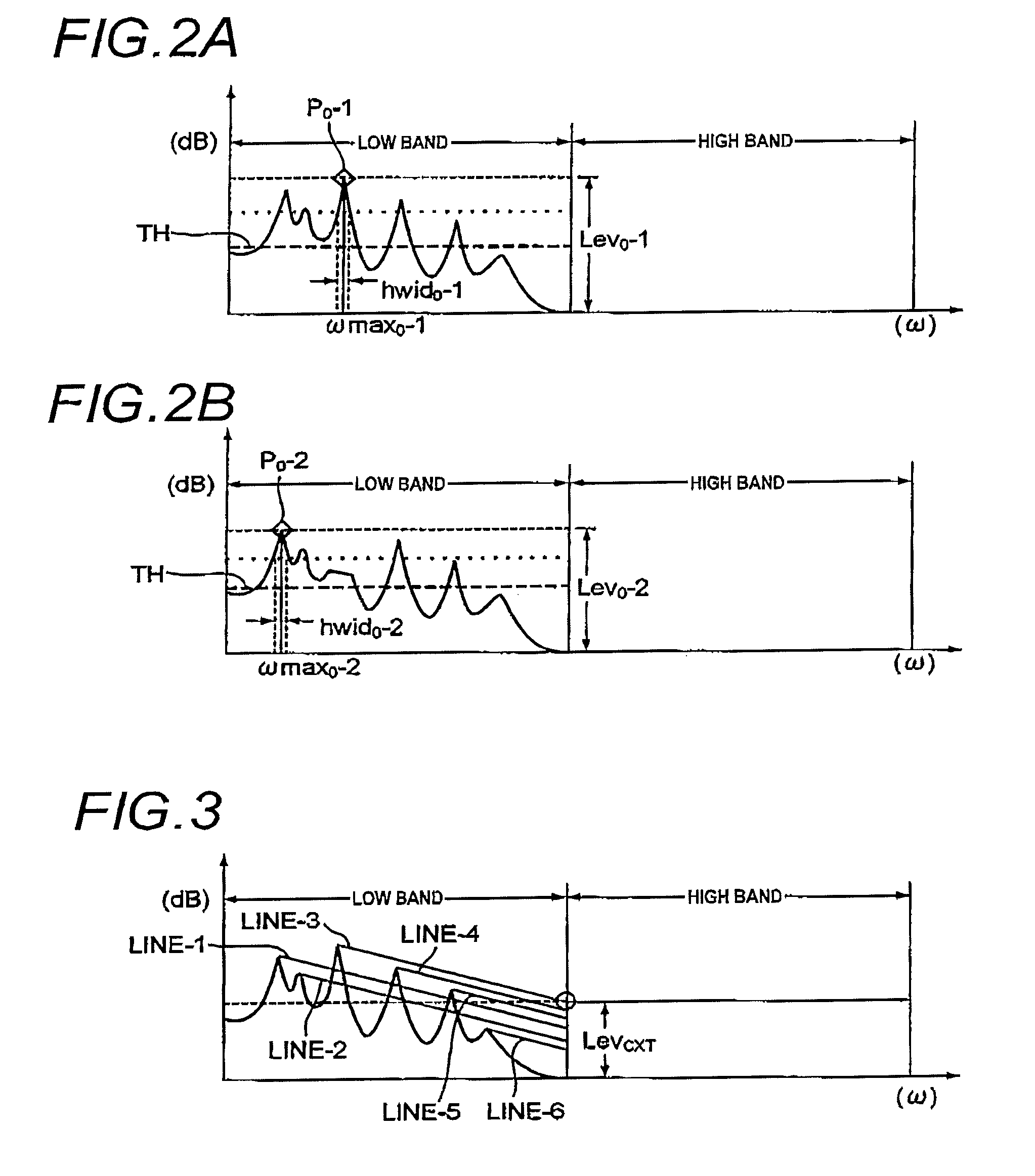
An anti-feedback device includes an anti-feedback filter provided in a closed loop. The anti-feedback device down-samples a signal of specific band selected from an output signal of an adaptive target signal transfer system and a signal of the same band selected from an input signal of the transfer system, and a filtering coefficient of the adaptive filter is updated by use of the down-sampled signals. The filter controller controls a filtering characteristic of the anti-feedback filter so that a peak gain of a frequency of an amplitude characteristic within a specific band of a closed loop determined from the filtering coefficient of the adaptive filter is suppressed. Moreover, the filter controller estimates a gain of the closed loop outside the specific band from the amplitude characteristic in the specific band and controls the amount of suppression of the anti-feedback filter outside the band in accordance with a result of estimation.

Description

BACKGROUND OF THE INVENTION[0001]1. Technical Field[0002]The present invention relates to an art for suppressing feedback by use of an adaptive filter.[0003]2. Background Art[0004]Occurrence of feedback causes problems in many cases in the field of an acoustic feedback system that amplifies a signal of sound collected within single acoustic space by means of a microphone and that emits the thus-amplified signal from a speaker. An anti-feedback device utilizing an adaptive filter is available as means for suppressing such feedback. Such an anti-feedback device generates from a signal input to the speaker a simulated signal that simulates a circulatory sound component, which originates from a speaker and enters a microphone, by means of an adaptive filter. The simulated signal is cancelled out by the signal output from the microphone. However, when a change arises in the state of a transmission system of circulatory sound, the adaptive filter consumes much time before outputting a sim...

Claims


Application Information

Patent Timeline
Patent Type & Authority Patents(United States)
IPC IPC(8): H04B15/00H04R27/00H04R25/00
CPCH04R3/02H04R2430/03
Inventor OKUMURA, HIRAKUTANAKA, HIROBUMI
Owner YAMAHA CORP
Learn More