
Audio wave field encoding

a wave field and audio technology, applied in the field of digital encoding and decoding, can solve the problems of inability to generate the correct spatial impression, inability to optimize the encoded audio data, and inability to optimize the encoded audio, etc., to achieve the effect of reducing the processing power of the decoder, and increasing the complexity of the decoder

Inactive Publication Date: 2012-07-10
ECOLE POLYTECHNIQUE FEDERALE DE LAUSANNE (EPFL)
View PDF11 Cites 12 Cited by
  • Summary
  • Abstract
  • Description
  • Claims
  • Application Information

AI Technical Summary

Benefits of technology

The present invention provides a method for encoding and decoding multiple audio channels using a two-dimensional filter-bank and a quantization remover. The encoded data includes a quantized two-dimensional spectra and a masking model that takes into account the frequency masking effect. The decoded data is transformed with a two-dimensional inverse filter-bank to reconstruct the original audio channels. The invention also includes an acoustic registration system for sampling and analyzing the acoustic wave field at multiple locations and storing the data as a compressed bitstream. The technical effects of the invention include improved spatial sound perception and reduced sound distortion.

Problems solved by technology

This is not the case in traditional multi-channel configurations, such as Stereo and Surround, which are not able to generate the correct spatial impression beyond an optimal location in the room—the sweet spot.
The fact that WFS requires a large amount of audio channels for reproduction presents several challenges related to processing power and data storage or, equivalently, bitrate.
Usually, optimally encoded audio data requires more processing power and complexity for decoding, and vice-versa.
These algorithms are, however very demanding in processing power for the decoder, which is therefore more expensive and complex.
The original sources, moreover, are not always available and, even when they are, it may not be desirable, from a copyright protection standpoint, to disclose them.
While these methods have been extremely successful for conventional mono, stereo, or surround audio recordings, they can not be expected to deliver optimal performance if applied individually to a large number of WFS audio channels.

Method used


Image

  • Audio wave field encoding
  • Audio wave field encoding
  • Audio wave field encoding

Examples


Embodiment Construction

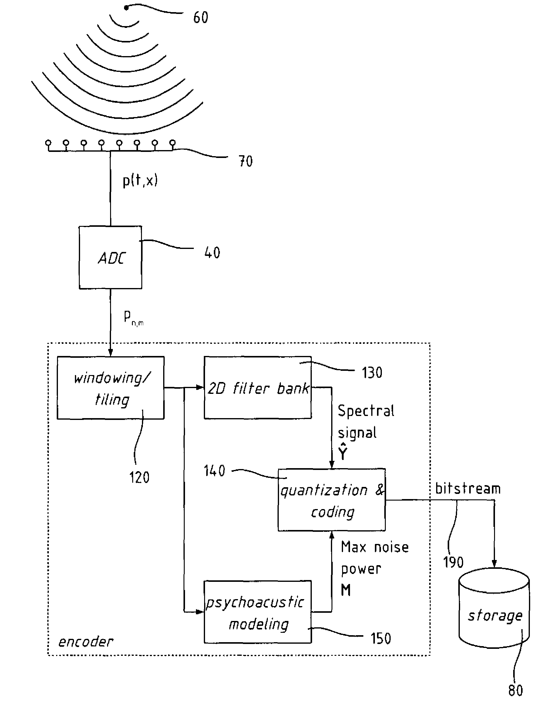
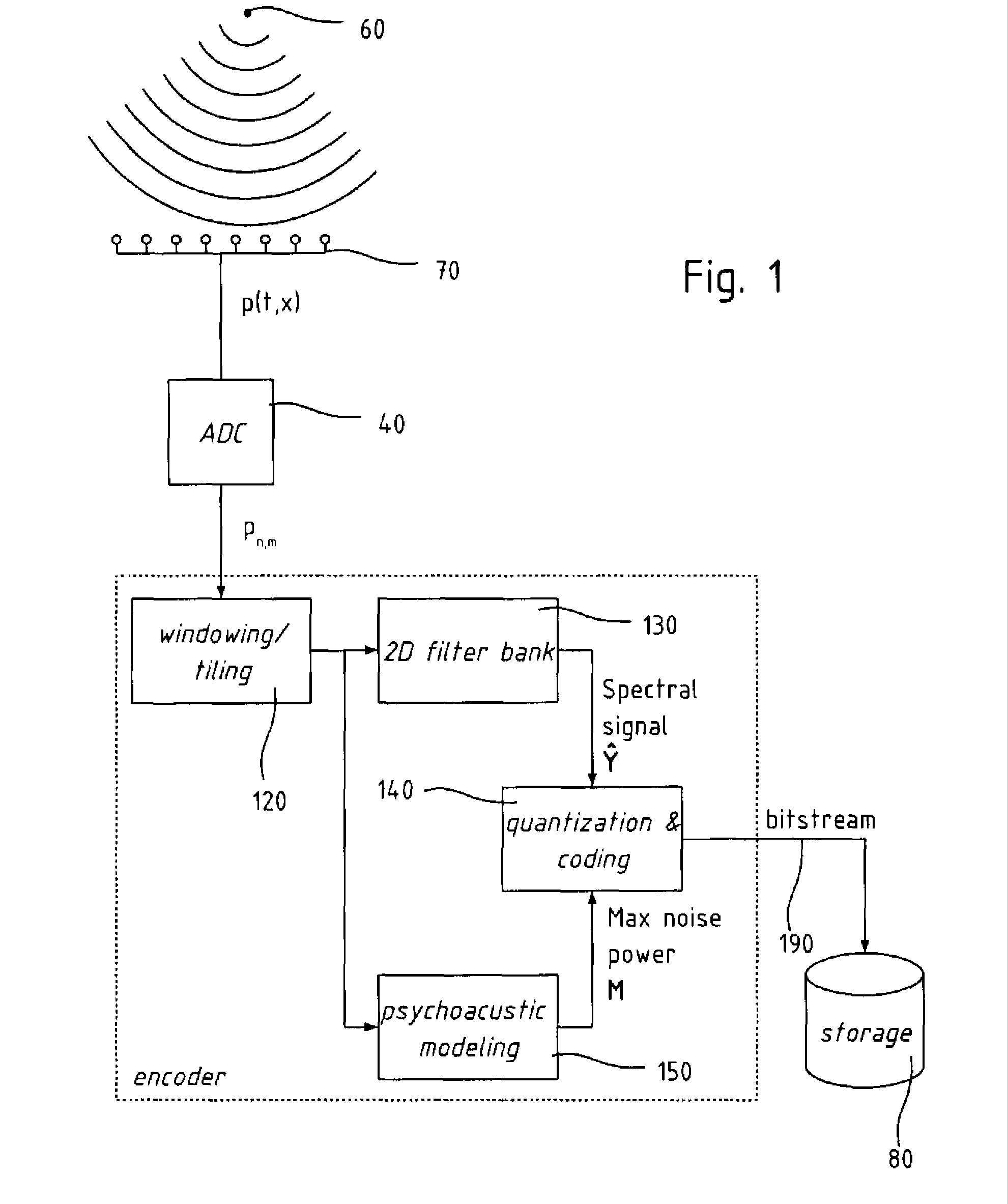
[0022]The acoustic wave field can be modeled as a superposition of point sources in the three-dimensional space of coordinates (x, y, z). We assume, for the sake of simplicity, that the point sources are located at z=0, as is often the case. This should not be understood, however, as a limitation of the present invention. Under this assumption, the three dimensional space can be reduced to the horizontal xy-plane. Let p(t,r) be the sound pressure at r=(x,y) generated by a point source located at rs=(xs,ys). The theory of acoustic wave propagation states that

[0023]p⁡(t,r)=1r-rs⁢s⁡(t-r-rsc)(1)

where s(t) is the temporal signal driving the point source, and c is the speed of sound. We note that the acoustic wave field could also be described in terms of the particle velocity v(t,r), and that the present invention, in its various embodiments, also applies to this case. The scope of the present invention is not, in fact, limited to a specific wave field, like the fields of acoustic pressu...


PUM


Abstract

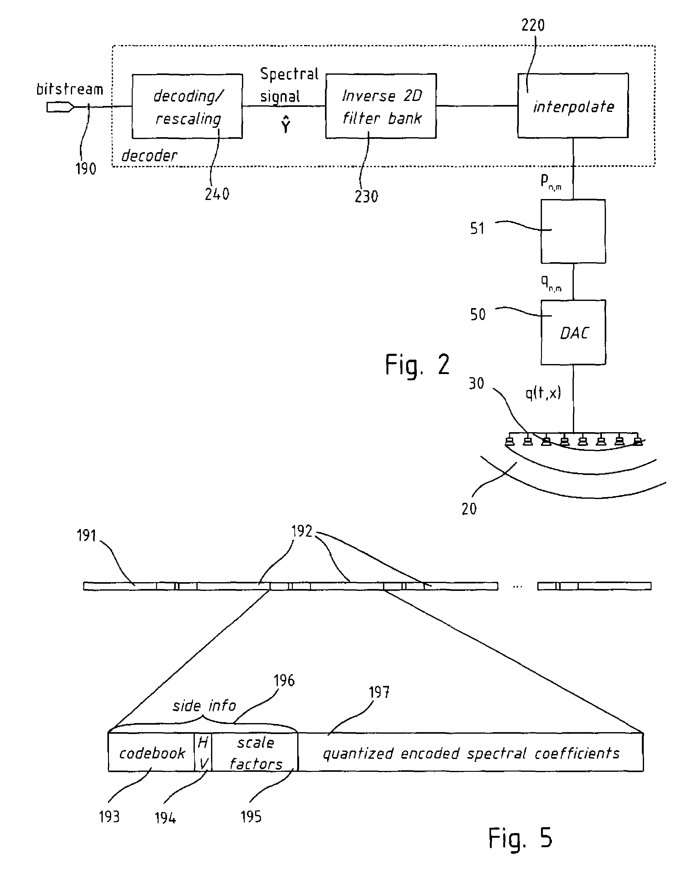
An encoder / decoder for multi-channel audio data, and in particular for audio reproduction through wave field synthesis. The encoder comprises a two-dimensional filter-bank to the multi-channel signal, in which the channel index is treated as an independent variable as well as time, and and the resulting spectral coefficient are quantized according to a two-dimensional psychoacoustic model, including masking effect in the spatial frequency as well as in the temporal frequency. The coded spectral data are organized in a bitstream together with side information containing scale factors and Huffman codebook identifiers.

Description

FIELD OF THE INVENTION[0001]The present invention relates to a digital encoding and decoding for storing and / or reproducing sampled acoustic signals and, in particular, signal that are sampled or synthesized at a plurality of positions in space and time. The encoding and decoding allows reconstruction of the acoustic pressure field in a region of area or of space.DESCRIPTION OF RELATED ART[0002]Reproduction of audio through Wave Field Synthesis (WFS) has gained considerable attention, because it offers to reproduce an acoustic wave field with high accuracy at every location of the listening room. This is not the case in traditional multi-channel configurations, such as Stereo and Surround, which are not able to generate the correct spatial impression beyond an optimal location in the room—the sweet spot. With WFS, the sweet spot can be extended to enclose a much larger area, at the expense of an increased number of loudspeakers.[0003]The WFS technique consists of surrounding the lis...

Claims


Application Information

Patent Timeline
Patent Type & Authority Patents(United States)
IPC IPC(8): G10L21/04G10L19/14G10L11/00G10L19/00G10L11/04G10L25/90
CPCG10L19/008G10L19/0204H04S3/008H04R5/027H04R2201/403H04S2420/13
Inventor VETTERLI, MARTINPEREIRA CORREIA PINTO, FRANCISCO
Owner ECOLE POLYTECHNIQUE FEDERALE DE LAUSANNE (EPFL)
Learn More