Inhalation system and method

Inactive Publication Date: 2012-07-17
US SEC THE ARMY ON BEHALF OF USAMRMC
View PDF71 Cites 8 Cited by
  • Summary
  • Abstract
  • Description
  • Claims
  • Application Information

AI Technical Summary

Benefits of technology

[0021]In one or more various embodiments, related systems include but are not limited to circuitry and/or programming for effecting the foregoing-referenced method embodiments; the circuitry and/or prog

Problems solved by technology

Each of these types of systems has drawbacks.
For example, in related-art dynamic inhalation systems the constant supply and exhaust of inhalant from the chamber results in low efficiency of inhalant delivery.
This results in a wasting of over 99% of the test material during the exposure.
Insofar as that most materials in pre-clinical trials or initial stages of animal testing are expensive to produce, and generally synthesized in small lots, the poor efficiency of related-art dynamic exposure systems imposes a heavy financial burden on organizations.
As another example of the drawbacks of related-art dynamic inhalation systems, consider that if a user were attempting to determine the toxicity or infectiousness of a highly pathogenic aerosol, a large amount of the test material would be expended in an attempt to achieve a dose to reach the desired outcome using a related-art dynamic system.
Accordingly, the amount of pathogen that needs to be aerosolized would be increased, thus potentially raising the safety risks to users of the system.
As another example of the drawbacks of dynamic inhalation systems, dynamic inhalation systems are unattractive for testing so-called “aged” aerosols.
Because of the high throughput of related-art dynamic inhalation systems, such systems often do not provide the longer inhalant residence times needed for these studies.
Related-art static inhalation systems have a number of drawbacks that make them unattractive for inhalation toxicology studies.
One drawback of related-art static inhalation systems is that related-art static inhalation systems do not provide a mechanism for real-time dose calculation.
There are no related-art static inhalation systems that allow the inhaled dose to be determined in near real-time during the exposure.
Another drawback of relate

Method used


Image

  • Inhalation system and method
  • Inhalation system and method
  • Inhalation system and method

Examples


Embodiment Construction

A. Introduction

[0026]The subject matter described herein entails a method and associated system for generating a cycle of dynamic and static test atmospheres designed to be used for aerosol characterization or exposing animals to all materials potentially aerosolized, but especially limited production materials such as new chemical entities or biologics. In one application, the method and system will greatly reduce the cost and time required for evaluation of precious materials under testing. The method and system include complete computer automated control (see herein incorporated by reference in its entirety U.S. Pat. No. 6,904,912 B2) of aerosol generation, characterization, and exposure duration and can be utilized with a variety of commercially-available aerosol generators, sampling devices, and material types.

[0027]1. System Hardware

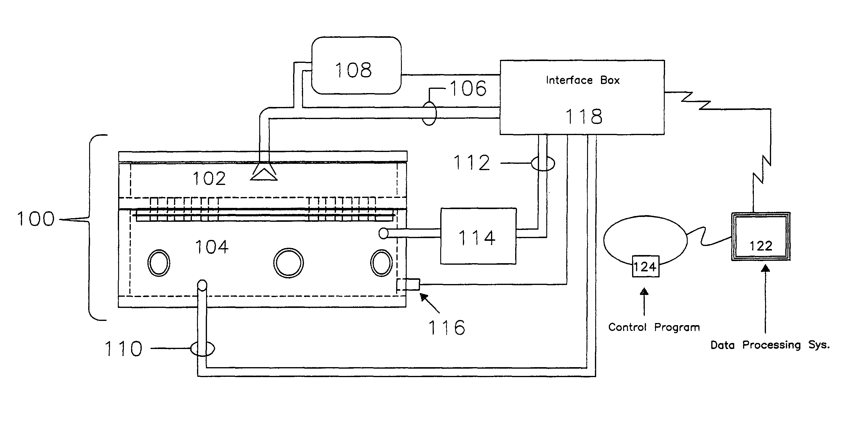
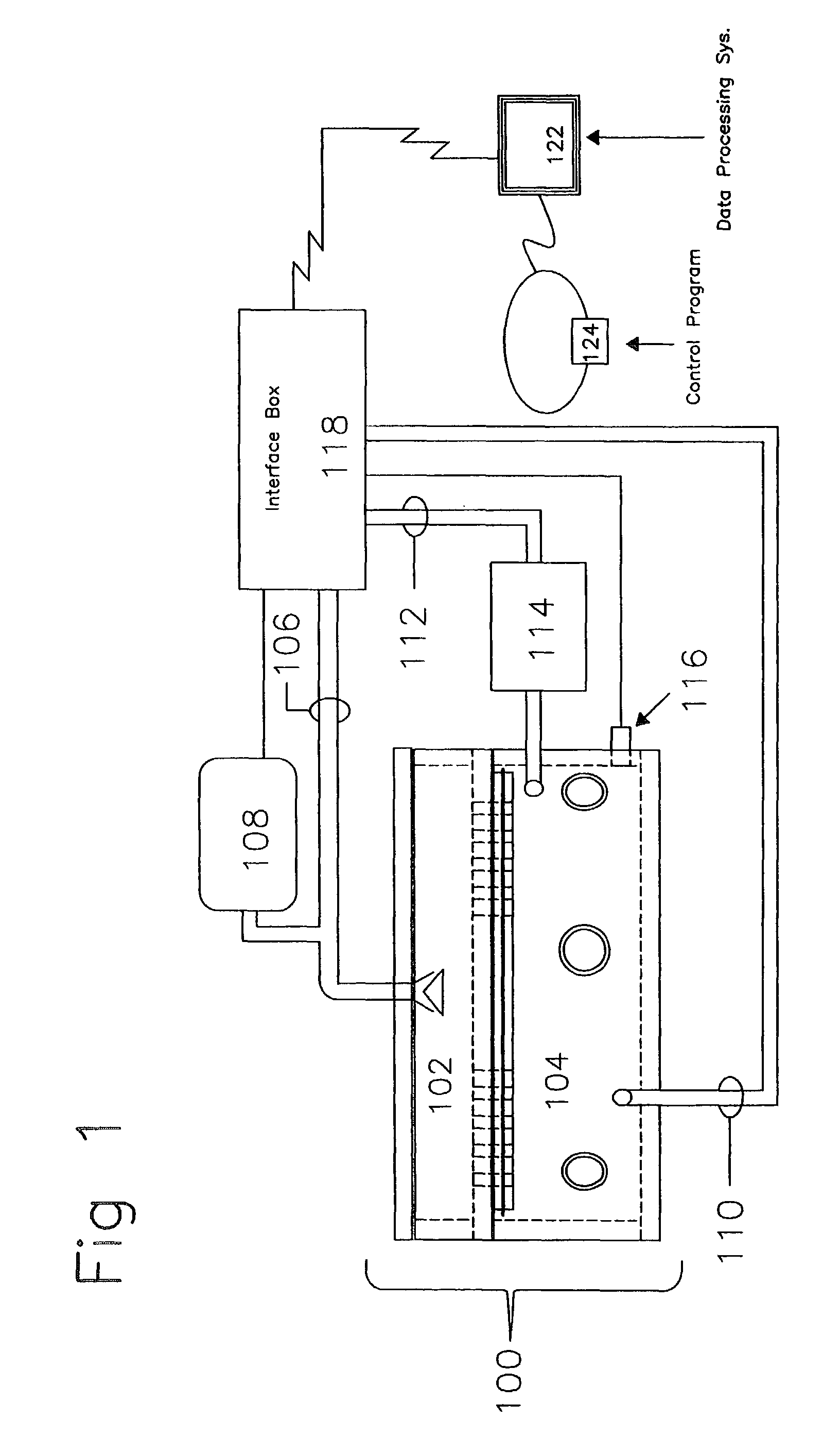
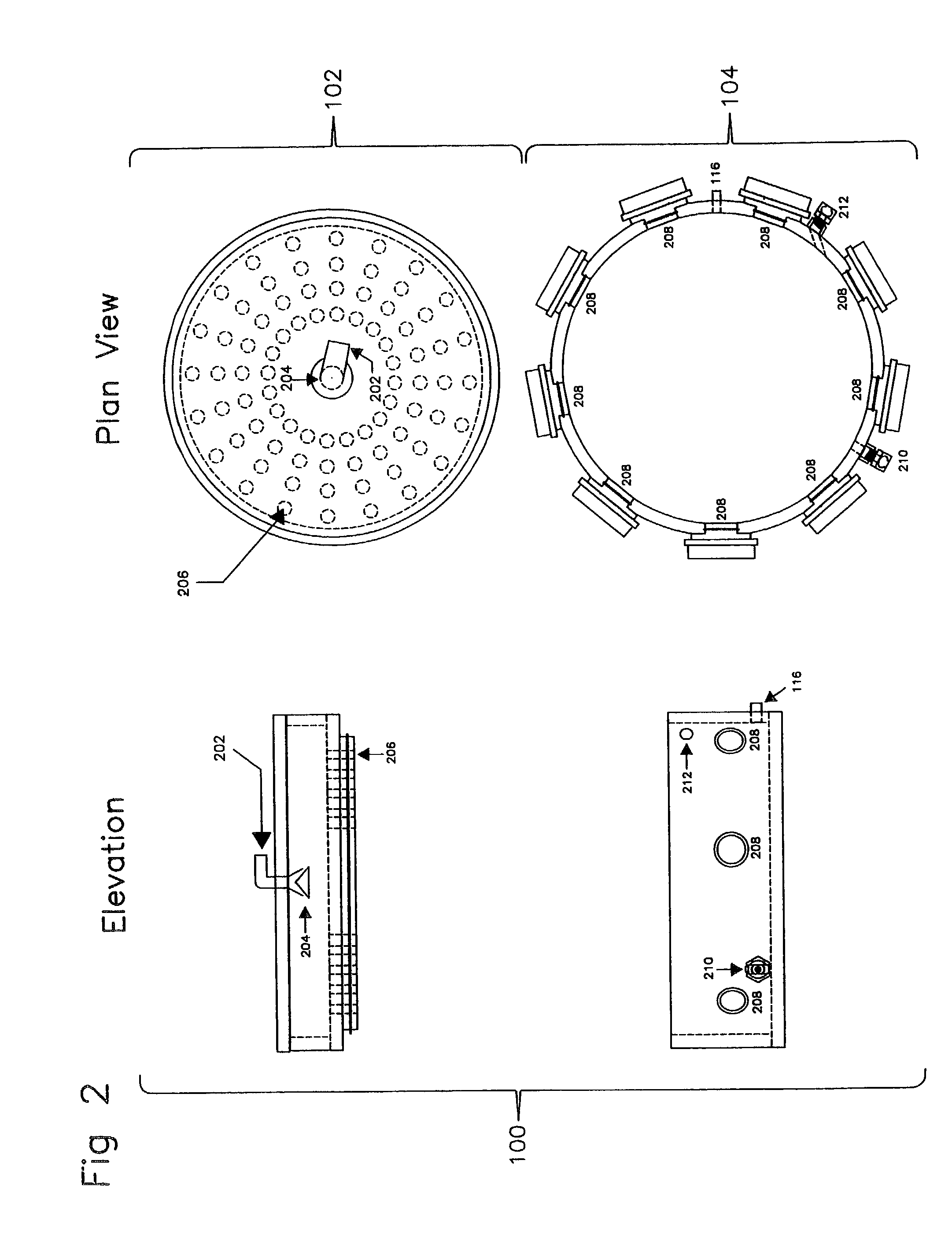
[0028]A high level pictographic representation of an exposure system and associated hardware is included as FIG. 1. Depicted is exposure chamber 1...


PUM


Abstract

A system includes but is not limited to at least one manifold; an inhalant dissemination device coupled to the at least one manifold; an inhalant characterization device coupled to the at least one manifold; and a control module operably coupled to the inhalant dissemination device and the inhalant characterization device, said control module configured to (a) determine an inhalant concentration in a manifold, and (b) calculate at least one of a retrospective and a prospective inhaled dose in response to the inhalant concentration, and (c) start and stop a flow through the manifold until the at least one of the retrospective and the prospective inhaled dose is greater than or equal to a specified dose. A method includes but is not limited to starting a flow of an inhalant through a manifold; determining an inhalant concentration of the inhalant in the manifold; and stopping the flow of the inhalant through the manifold when the inhalant concentration is in a first specified inhalant-concentration range.

Description

CROSS-REFERENCE TO RELATED APPLICATION[0001]This application claims the benefit under 35 U.S.C. 119(e) of, and incorporates by reference in its entirety the presently U.S. Provisional Patent Application No. 60 / 396,698,entitled Hybrid Inhalation System for Precious Materials, filed 17 Jul. 2002,naming Justin M. Hartings, Chad J. Roy, and Gerald M. Liverette as inventors.[0002]This application is also a continuation in part of, claims priority from, and incorporates by reference in its entirety the presently U.S. patent application Ser. No. 09 / 919,741, filed 31 Jul. 2001, entitled AUTOMATED INHALATION TOXICOLOGY EXPOSURE SYSTEM, now U.S. Pat. No. 6,904,912 B2, issued on 14 Jun. 2005, naming Justin M. Hartings, and Chad J. Roy as inventors.[0003]This application is also a continuation in part of, claims priority from, and incorporates by reference in its entirety the presently U.S. patent application Ser. No. 10 / 166,228, filed 29 May 2002, now U.S. Pat. No. 7,377,276, entitled INHALANT...

Claims


Application Information

Patent Timeline
IPC IPC(8): A61B5/08A01K1/03A61D7/04
CPCA01K1/031A61D7/04A61B5/0806
Inventor HARTINGS, JUSTIN M.ROY, CHAD J.LIVERETTE, GERALD M.
Owner US SEC THE ARMY ON BEHALF OF USAMRMC
Why Eureka
Try Eureka