
Eureka
For R&D, Eureka makes reading and utilizing patents & technical documents easy.
Eureka AIR
Designed for self-driven R&D workflows. Generate viable solutions, solve complex R&D challenges, empower your innovation with AI.

Eureka Materials
Designed for material experts only. Revolutionize your material R&D, from search, analyze, to developing new materials.

TechResearch
Generate reliable direction feasibility study reports for your R&D in just a few steps.

TechSeek
Discover and master advanced knowledge NOW. Basics, ideas, possibilities, all at once.

TechMind
As an expert in R&D Theories, TechMind can generates customized viable solutions instantly.

TechRisk
Analyze your overall solution with one click, know your potential R&D risks in advance.

TechMonitor
Get weekly tech updates, stay abreast of the latest tech innovations and key insights.
Infection-blocking dental implant
- Summary
- Abstract
- Description
- Claims
- Application Information
AI Technical Summary
Benefits of technology
Problems solved by technology
Method used
Image

Examples
example no.1
EXAMPLE NO. 1
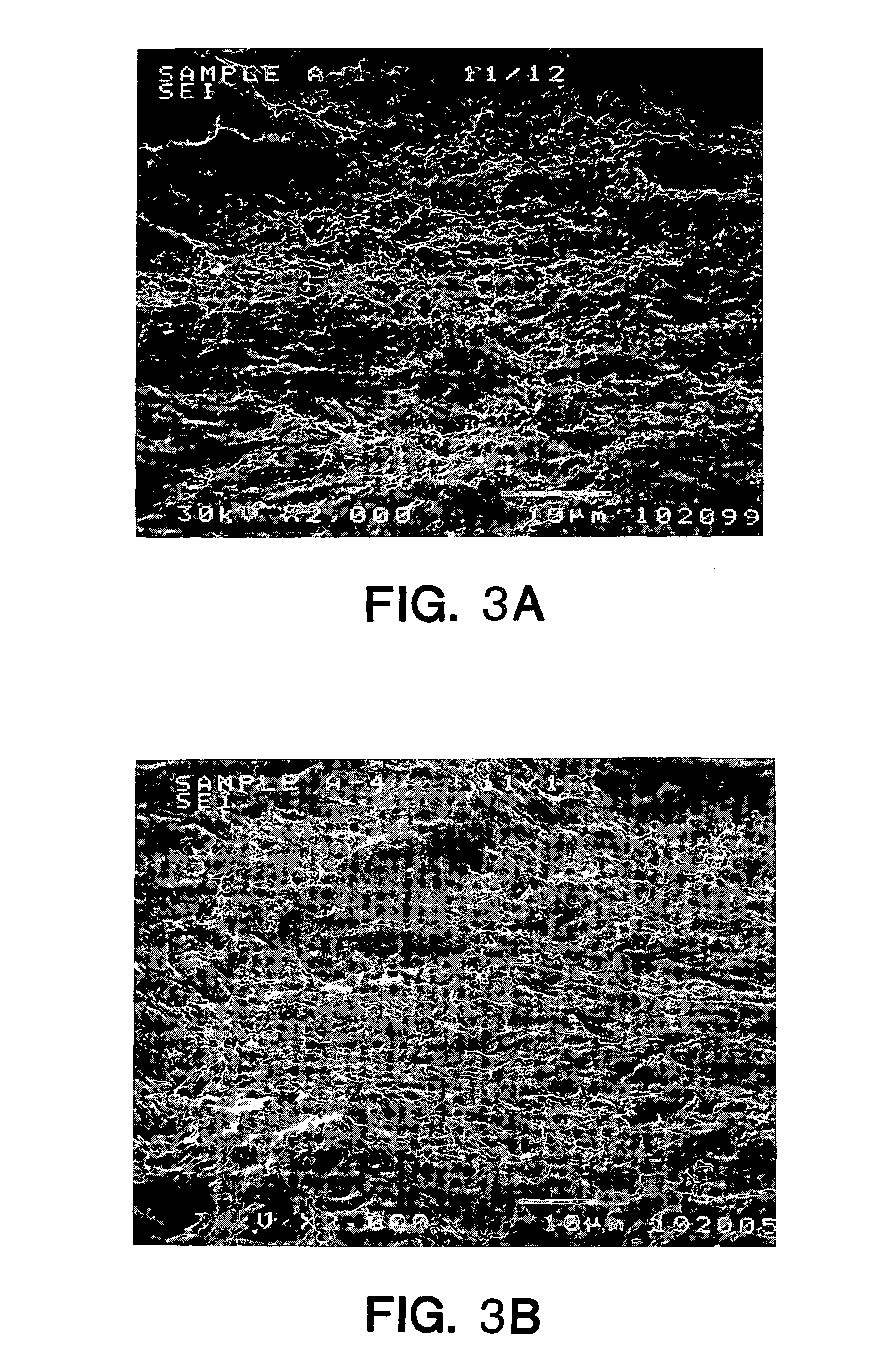
[0036]A batch of 30 screw-type cylindrical implants made of CP titanium were grit blasted using particles of CP B299 SL grade titanium grit having particle sizes ranging from 10 to 45 microns, at a pressure of 60 to 80 psi. After grit-blasting, native oxide layer was removed from the implant surfaces by placing 4 implants in 100 ml. of a 15% solution of HF in water at room temperature for 30 seconds. The implants were then removed from the acid, neutralized in a solution of baking soda, and placed in 150 ml. of “Modified Muriaticetch” (described above) at room temperature for 3 minutes. The implants were then removed from the acid, neutralized, rinsed and cleaned. All samples displayed very similar surface topographies and a high level of etch uniformity over the surface, when compared with each other in SEM evaluations. Consistency in the surface features (peaks and valleys) was also observed. The SEMs in FIGS. 3A, 3B, 4A and 4B show the surfaces of two of the implants...
example no.2
EXAMPLE NO. 2
[0040]Four of the implants that had been grit blasted as described in EXAMPLE NO. 1 above were placed in 150 ml. of “Modified Muriaticetch” for 10 minutes. The implants were then removed, neutralized, rinsed and cleaned. SEM photographs taken at magnifications of 2,000 and 20,000 showed that the bulk etch solution failed to remove the native oxide layer after 10 minutes in the etch solution. The failure to remove the native oxide layer (100-150 Angstrom units thick) resulted in a non-uniformly etched surface, as depicted for example in FIG. 3 of U.S. Pat. No. 5,876,453. In areas of the implant surfaces where the native oxide was removed, the topography was similar to that observed on the implants in EXAMPLE NO. 1.
example no.3
EXAMPLE NO. 3
[0041]The procedure of this example is currently preferred for producing commercial implants. A batch of screw-type implants made of CP titanium were immersed in a 15% solution of HF in water at room temperature for 60 seconds to remove the native oxide layer from the implant surfaces. A plastic cap was placed over the top of each implant to protect it from the acid. The implants were then removed from the acid and rinsed in a baking soda solution for 30 seconds with gentle agitation. The implants were then placed in a second solution of baking soda for 30 seconds, again with agitation of the solution; and then the implants were rinsed in deionized water. Next the implants were immersed in another solution of two parts by volume sulfuric acid (96% by weight H2 SO4, 4% by weight water),and one part by volume hydrochloric acid (37% by weight HCl, 63% by weight water) at 70° C. for 5 minutes. The implants were then removed from the acid and rinsed and neutralized by repeat...
PUM
| Property | Measurement | Unit |
|---|---|---|
| Length | aaaaa | aaaaa |
| Acidity | aaaaa | aaaaa |
Abstract
Description
Claims
Application Information
 - R&D Engineer
- R&D Manager
- IP Professional
- Industry Leading Data Capabilities
- Powerful AI technology
- Patent DNA Extraction
Browse by: Latest US Patents, China's latest patents, Technical Efficacy Thesaurus, Application Domain, Technology Topic, Popular Technical Reports.
© 2024 PatSnap. All rights reserved.Legal|Privacy policy|Modern Slavery Act Transparency Statement|Sitemap|About US| Contact US: help@patsnap.com