System and method for 3D imaging using structured light illumination

a structured light and illumination technology, applied in the field of biometrics, can solve the problems of poor quality of finger prints and palm prints, slow and cumbersome rolled ink print technique, and many limitations of the above-described known process of rolling inked fingerprints, and achieve the effect of increasing the speed of handprint image acquisition and being more robust to extremely worn ridges of fingers

Inactive Publication Date: 2012-07-17
UNIV OF KENTUCKY RES FOUND
View PDF6 Cites 83 Cited by
  • Summary
  • Abstract
  • Description
  • Claims
  • Application Information

AI Technical Summary

Benefits of technology

[0014]This embodiment of the biometrics system has many advantages such as the speed of acquisition of the handprint images is greatly increased. Translucent sweat or oil will not corrupt the handprint images nor will common variations in skin color. Th...

Problems solved by technology

Though the need for accurate and fast biometric identification is increasing, the above described known process of rolling an inked fingerprint has many limitations.
The rolled ink print technique is slow and cumbersome and often produces finger prints and palm prints of poor quality.
It requires a trained technician to grasp and manipulate a person's finger or hand, and even then it may take multiple attempts to successfully capture a print that meets industry standards.
The rolled finger prints and palm prints can o...

Method used


Image

  • System and method for 3D imaging using structured light illumination
  • System and method for 3D imaging using structured light illumination
  • System and method for 3D imaging using structured light illumination

Examples


Embodiment Construction

[0031]The present invention is best understood in relation to FIGS. 1 through 15 of the drawings, like numerals being used for similar elements of the various drawings. The following description includes various specific embodiments of the invention but a person of skill in the art will appreciate that the present invention may be practiced without limitation to the specific details of the embodiments described herein.

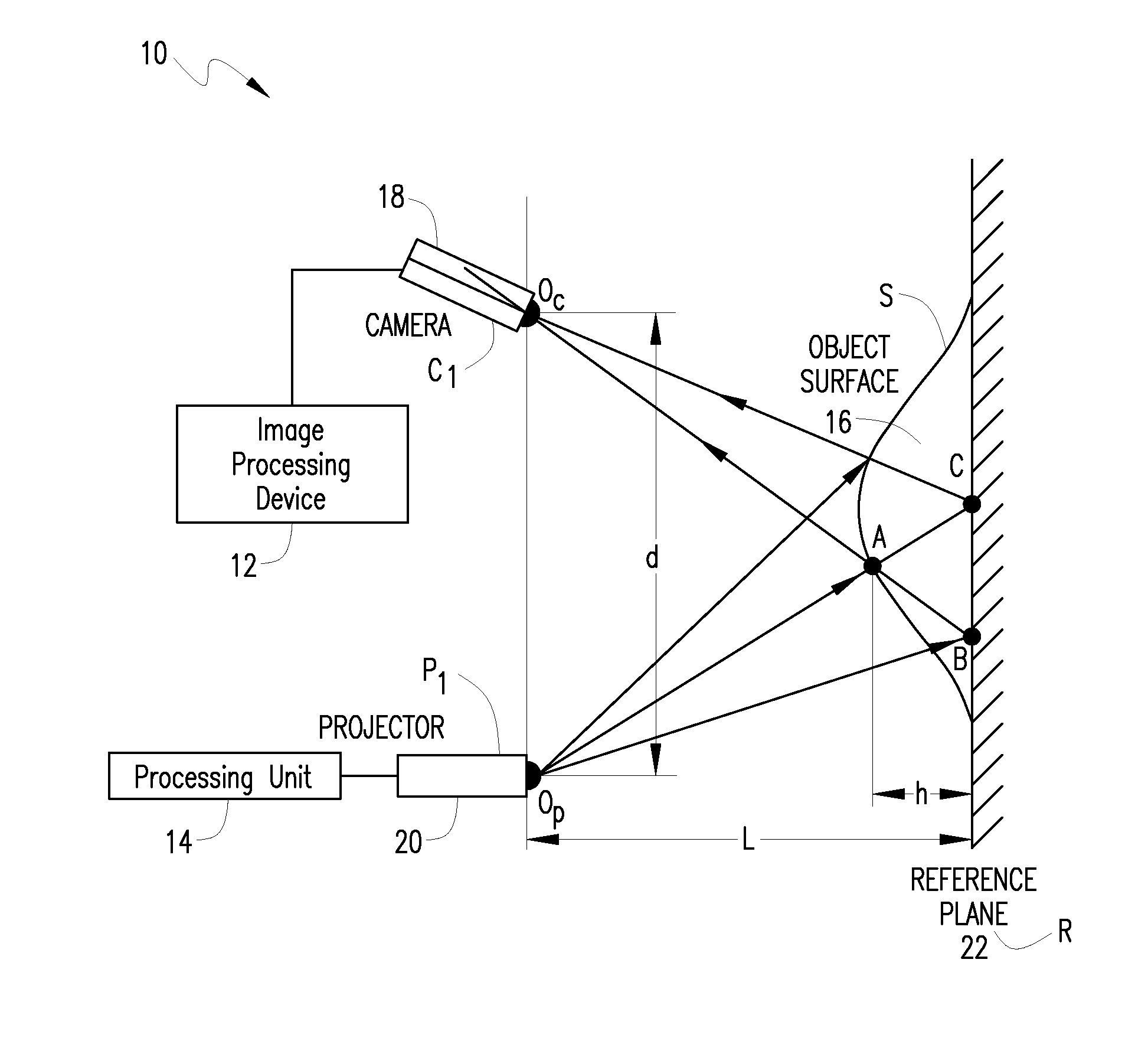
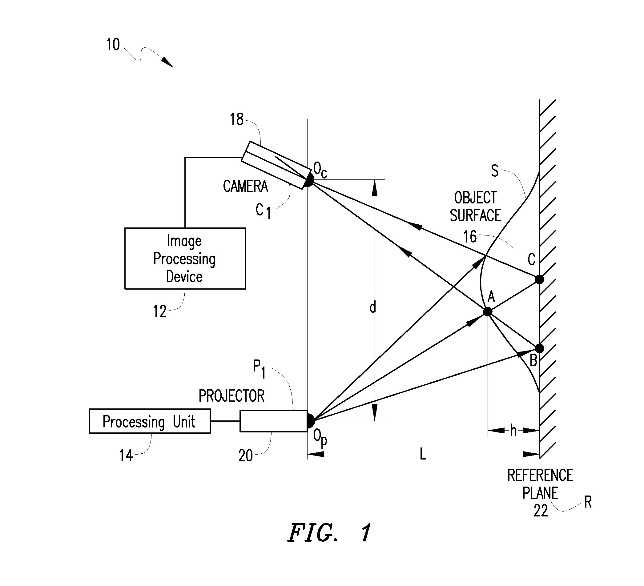
[0032]One approach to creating a 3D image is called a structured light illumination (SLI) technique. In SLI technique, a light pattern is projected onto a 3D object surface. FIG. 1 shows an example SLI system 10. In FIG. 1, the SLI system 10 includes a camera 18 and projector 20. The 3D object 14 is placed at a reference plane 22 that is a predetermined distance L from the projector 20 and camera 18. In this example, the projector 20 and camera 18 are in the same plane with respect to each other to simplify calculations, but such positioning is not required.

[0033]In us...


PUM


Abstract

A biometrics system captures and processes a handprint image using a structured light illumination to create a 2D representation equivalent of a rolled inked handprint. The biometrics system includes an enclosure with a scan volume for placement of the hand. A reference plane with a backdrop pattern forms one side of the scan volume. The backdrop pattern is preferably a random noise pattern and the coordinates of the backdrop pattern are predetermined at system provisioning. The biometrics system further includes at least one projection unit for projecting a structured light pattern onto a hand positioned in the scan volume on or in front of the backdrop pattern and at least two cameras for capturing a plurality of images of the hand, wherein each of the plurality of images includes at least a portion of the hand and the backdrop pattern. A processing unit calculates 3D coordinates of the hand from the plurality of images using the predetermined coordinates of the backdrop pattern to align the plurality of images and mapping the 3D coordinates to a 2D flat surface to create a 2D representation equivalent of a rolled inked handprint. The processing unit can also adjust calibration parameters for each hand scan from calculating coordinates of the portion of backdrop pattern in the at least one image and comparing with the predetermined coordinates of the backdrop pattern.

Description

RELATED APPLICATIONS[0001]This application claims benefit under 35 U.S.C. 120 of prior provisional application Ser. No. U.S. 60 / 730,185 filed on Oct. 25, 2005, which is incorporated by reference herein.STATEMENT REGARDING FEDERALLY SPONSORED RESEARCH OR DEVELOPMENT[0002]The U.S. Government has a paid up license in this invention and the right in limited circumstances to require the patent owner to license others on reasonable terms as provided for by the terms of Contract No. 2004-IJ-CX-K055 awarded by the National Institute of Justice, through subcontract with Eastern Kentucky University Contract: 06-202.[0003]This application claims benefit under 35 U.S.C. 120 as a continuation in part application of prior, copending U.S. patent application Ser. No. 10 / 444,033, entitled, “System and Technique for Retrieving Depth Information about a Surface by Projecting a Composite Image of Modulated Light Patterns,” by Laurence G. Hassebrook, Daniel L. Lau, and Chun Guan filed on May 21, 2003, w...

Claims


Application Information

Patent Timeline
IPC IPC(8): G06K9/00G06V10/145
CPCG01B11/2513G06K9/2036G06T7/0057H04N13/0203G06K9/00006G06K9/00201G06T2207/30196G06K2209/40Y10S902/03G06K2209/401G06T7/521H04N13/204H04N13/254G06V10/145G06V2201/121G06V2201/12G06V20/64G06V40/12G06F18/00G01B11/254
Inventor HASSEBROOK, LAURENCE G.LAU, DANIEL L.DIETZ, HENRY G.
Owner UNIV OF KENTUCKY RES FOUND
Why Eureka
Try Eureka