
Paint robot and paint cartridge

a technology of coating robot and paint cartridge, which is applied in the direction of packaging foodstuffs, instruments, packaged goods, etc., can solve the problems of degrading the insulation performance of the actuating liquid, high voltage applied to the electrostatic paint and high voltage applied to the applicator externally leaks through the actuating liquid

Active Publication Date: 2012-07-24
CARLISLE FLUID TECH RANSBURG JAPAN KK
View PDF14 Cites 10 Cited by
  • Summary
  • Abstract
  • Description
  • Claims
  • Application Information

AI Technical Summary

Benefits of technology

"The present invention provides a coating robot with a cartridge-type electrostatic paint applicator that can supply paint to the applicator by squeezing the paint bag in a paint cartridge with an actuating liquid. The actuating liquid is supplied to the paint cartridge through a conduit in the robotic arm and is important in preventing high voltage applied to the applicator from leaking out through the liquid. The robot also has a tank for supplying the actuating liquid and a pump to supply the liquid under pressure to the paint cartridge. The invention also provides a coating robot with a tank for supplying the actuating liquid and a selectable passageway for either supplying the liquid to the paint cartridge or cleaning the applicator. The technical effects of the invention are improved prevention of leakage of high voltage and reliable insulation performance of the actuating liquid."

Problems solved by technology

Since the actuating liquid is supplied to the paint cartridge through the coating robot, here is the possibility that the high voltage applied to the electrostatic paint applicator externally leaks through the actuating liquid.
In a coating robot having a cartridge-type electrostatic paint applicator as disclosed in Patent Documents 1 to 3, in which a paint is supplied to the applicator from a paint cartridge by supplying an actuating liquid to the paint cartridge through a conduit in a robotic arm and thereby squeezing the paint bag in the paint cartridge either directly or indirectly, it may occur that a high voltage applied to the applicator leaks externally through the actuating liquid.
Further, even though an actuating liquid excellent in electrical insulation, there remain the problem that the insulation performance of the actuating liquid degrades as it is contaminated.

Method used


Image

  • Paint robot and paint cartridge
  • Paint robot and paint cartridge
  • Paint robot and paint cartridge

Examples


first embodiment

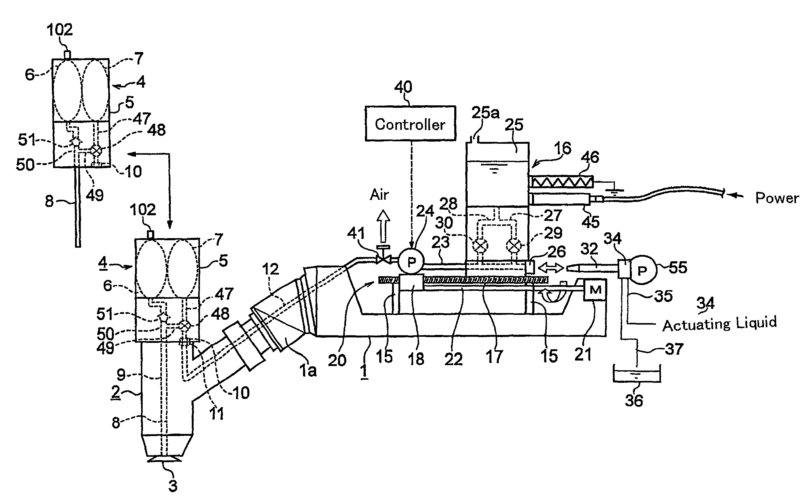
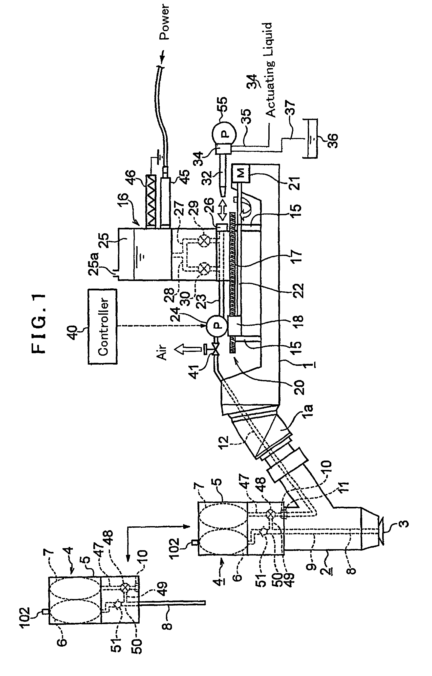
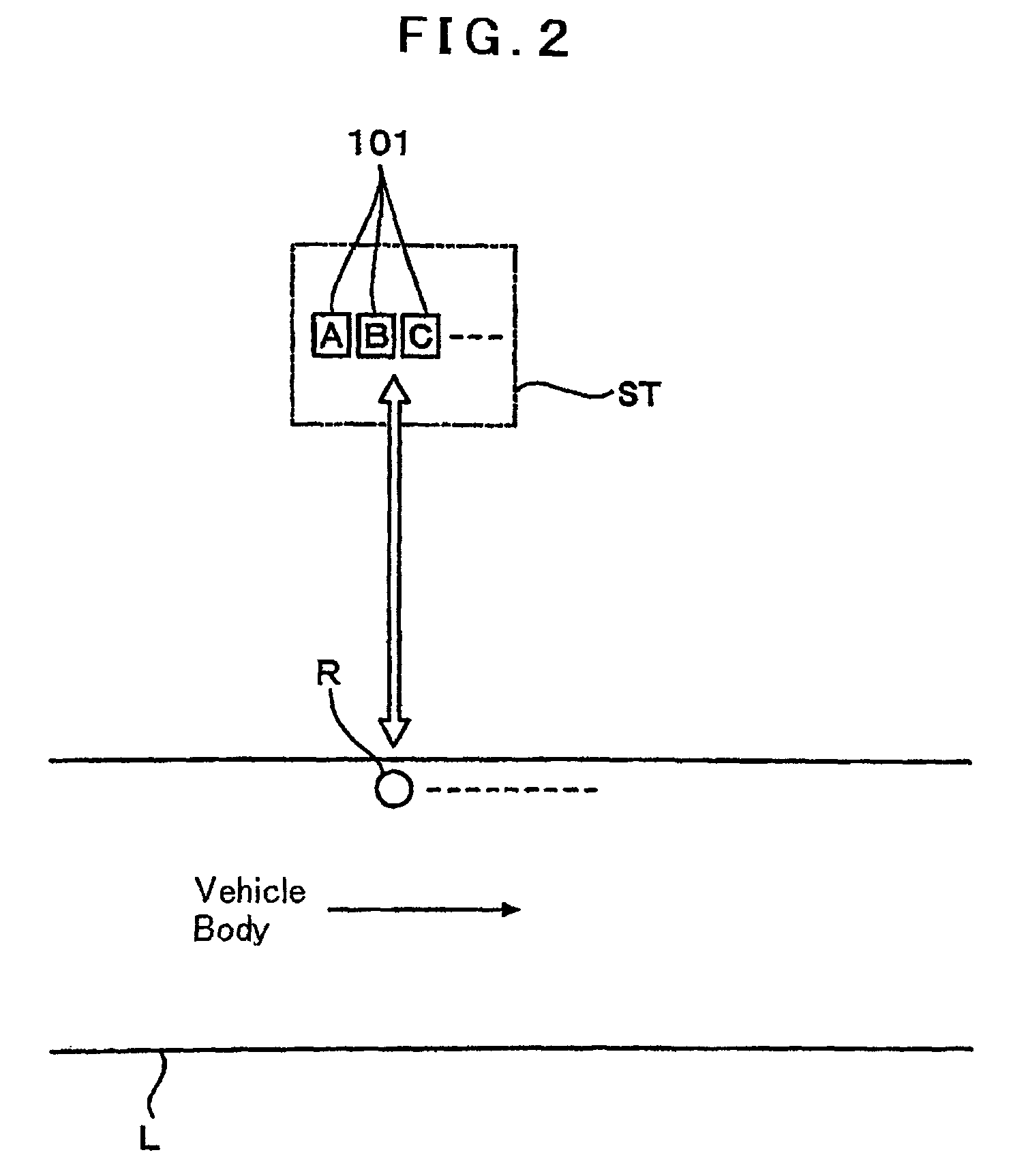
[0057]FIG. 1 shows a general aspect of a coating robot R according to the invention usable with a water-borne paint as a typical one of electrically conductive paints. In FIG. 1, reference numeral 1 denotes a robotic arm. As shown in FIG. 2, the painting robot R is set on a coating line L for electrostatic coating of vehicles. A paint refill station ST is provided in an area adjacent to the coating line L, to which the painting robot R can move. In the paint refill station ST, support seats 101 for color A, color B, color C, et seq., which will be explained later, are provided in a region where the robotic arm 1 of the coating robot R reaches.

[0058]As being well known, the coating robot R includes a robotic arm at an upper end of a column standing on a pedestal and capable of swinging and pivotal movements. An electrostatic paint applicator 2 is removably attached to a polyarticular wrist portion 1a at a distal end of the robotic arm 1. The electrostatic paint applicator 2 may be of...

second embodiment (fig.5)

[0091]Second Embodiment (FIG. 5)

[0092]FIG. 5 shows a coating robot according to a second embodiment of the invention. This embodiment is a modification of the above-explained first embodiment as well. Shown in FIG. 4 is an electrostatic paint applicator 200 having a high voltage generator 45 inside. Instead, however, the high voltage generator 45 may be provided in the robotic arm 1 as known in the art. A high voltage is supplied from the high voltage generator 45 to the bell cup 3 by a metallic conductor (not shown) like in existing systems. The high voltage generator 45 is supplied with power via a low voltage cable 120 provided in the robotic arm 1.

[0093]In the second embodiment as well, the tank 25 contains water as an actuating liquid. However, the second embodiment may be modified to use an electrically insulating liquid (typically an insulating thinner) as the actuating liquid, and the tank 25 may contain the insulating thinner.

[0094]The tank 25 is fixed on the robotic arm 1 ...

second embodiment

[0100]Also for the actuating liquid supply tube 12, table 15 and main pipe 23, these elements need not be made of insulating materials. The table 15, however, is preferably made of an insulating material. An insulating table 15 will prevent external leakage of the high voltage via contamination by the insulating thinner when the thinner comes to leak from the tank for a certain cause. This is applicable also to the second embodiment when it employs an insulating thinner as the actuating liquid.

[0101]In the above-described structures, the electrostatic paint applicator 2 and the various valves in the robotic arm 1 may be controlled electrically by signals output from the controller 40, or may be controlled by air.


PUM

PropertyMeasurementUnit
pressureaaaaaaaaaa
electrically insulatedaaaaaaaaaa
electrically insulatingaaaaaaaaaa

Abstract

An arm of a coating robot is used to prevent external leakage of a high voltage. A tank is installed on a robotic arm and contains water as an actuating liquid. The water is supplied to a paint cartridge by a pump controlled by a controller. The water sent from the pump under pressure is supplied to the paint cartridge by a conduit tube. A high voltage generator and a bleeder resistor are combined with the tank such that a high voltage generated by the high voltage generator is supplied to the electrostatic paint applicator via the water. For replenishment of water to the tank is attained by relatively connecting a nozzle in communication with a water source to a main pipe. While the high voltage generator generates a high voltage, the nozzle and the main pipe are kept disconnected to maintain electrical insulation between the nozzle and the main pipe.

Description

RELATED APPLICATIONS[0001]The present application is national phase of PCT / JP2008 / 070025 filed Nov. 4, 2008, and claims priority from Japanese Application Number 2007-308434 filed Nov. 29, 2007, the disclosures of which are hereby incorporated by reference herein in their entirety.FIELD OF THE INVENTION[0002]The present invention relates to a coating robot and a paint cartridge.BACKGROUND OF THE INVENTION[0003]Cartridge-type electrostatic paint applicators are known as being suitable for use with electrically conductive paints such as water-borne paints and metallic paints. Patent documents 1 to 3 disclose cartridge-type electrostatic paint applicators. These cartridge-type electrostatic paint applicators make it easy to prevent high-voltage leak, which is the phenomenon that a high voltage applied to an electrostatic applicator externally leaks through an electrically conductive paint.[0004]A typical cartridge-type electrostatic applicator has a paint cartridge detachably attached ...

Claims


Application Information

Patent Timeline
Patent Type & Authority Patents(United States)
IPC IPC(8): B05B3/00B05B3/04B05B5/025B67D7/00
CPCB05B5/1625B05B15/025B05B12/1463B05B9/047B05B15/55
Inventor MITSUI, MICHIOTANI, RYUJIINOSE, SADAO
Owner CARLISLE FLUID TECH RANSBURG JAPAN KK
Learn More