
Pneumatic mechanical power source

a pneumatic motor and pneumatic technology, applied in the direction of engine-driven generators, propulsion parts, vehicle sub-unit features, etc., can solve the problems of increasing the dependence on increasingly expensive non-renewable fossil fuels, unavoidable emission of carbon dioxide, and enormous waste of fossil fuel chemical energy in the form of heat, so as to reduce the dependence on fossil fuels, eliminate fossil fuels, and eliminate fossil fuels

Active Publication Date: 2012-07-24
DOMES TIMOTHY J
View PDF41 Cites 18 Cited by
  • Summary
  • Abstract
  • Description
  • Claims
  • Application Information

AI Technical Summary

Benefits of technology

This solution provides a highly efficient and environmentally friendly alternative by converting compressed gas energy directly into mechanical energy, reducing energy waste and emissions, and offering a scalable solution for various applications including transportation and HVAC systems.

Problems solved by technology

Among the huge disadvantages in the conventional fossil-fuel based motive power systems are (1) dependence on increasingly expensive non-renewable fossil fuels as a primary source of energy; (2) unavoidable emission of carbon dioxide as a combustion by-product; and (3) unavoidable enormous waste of the chemical energy of the fossil fuel in the form of heat (every heat engine has a radiator or some other form of heat dissipation means.
The heat energy unavoidably dissipated by heat engines constitutes waste of a substantial portion of the energy original contained within the fuel being consumed).
The remaining 78% of the energy is wasted, chiefly in the form of heat.
Failure to quickly remove waste heat from an internal combustion engine will result in overheating and engine destruction due to seize-up.
Since the atmosphere is thermally disturbed and chemically polluted by dumping of waste heat and carbon dioxide from conventional internal combustion engines.
However, transportation is not the only field in which internal combustion or fossil fuel combustion may be replaced by a compressed-gas-driven rotary pneumatic motor.
Industrial applications almost always have energy requirements, and may involve intense use of energy.

Method used


Image

  • Pneumatic mechanical power source
  • Pneumatic mechanical power source
  • Pneumatic mechanical power source

Examples


Embodiment Construction

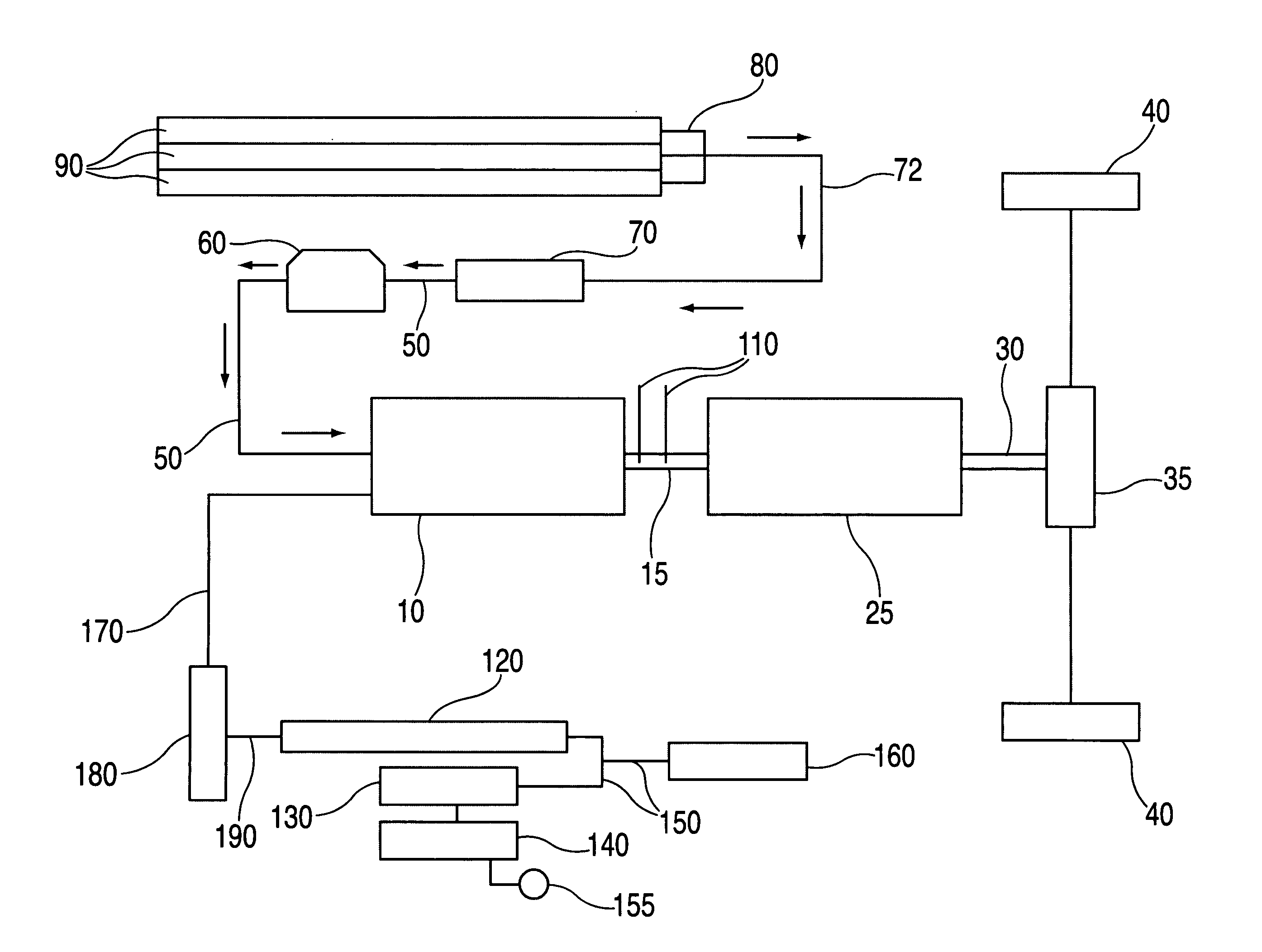
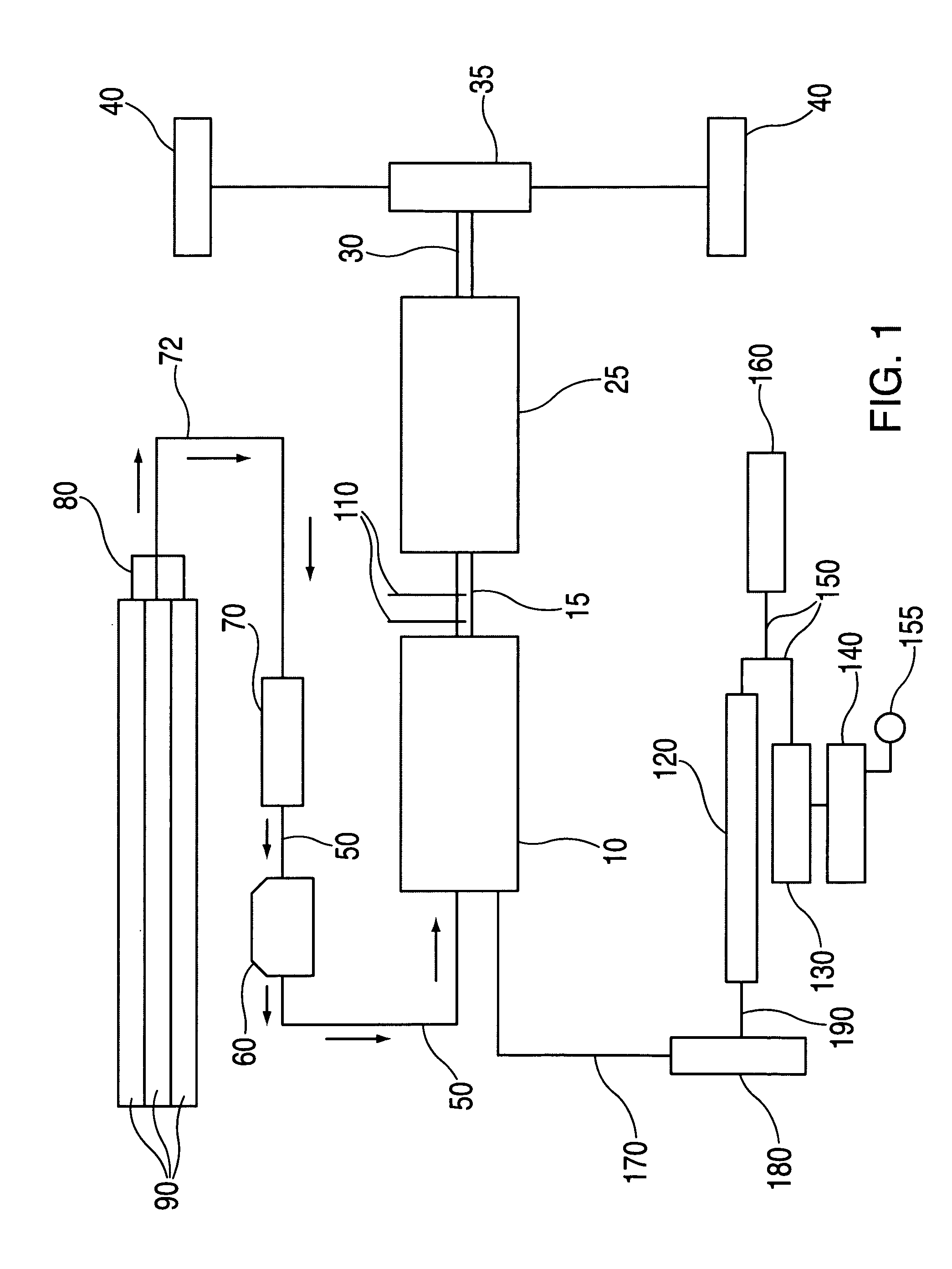
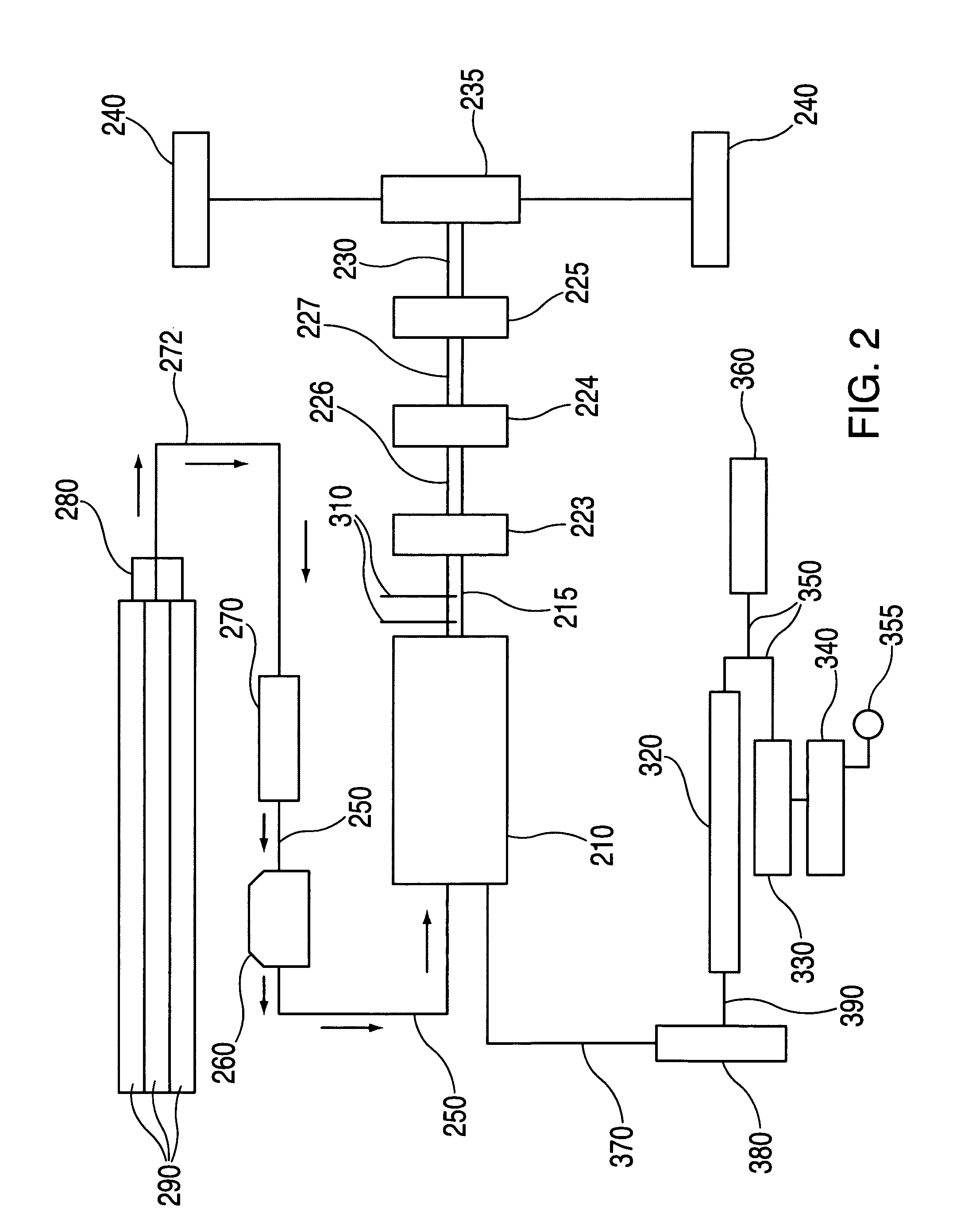
Number 1 of the present invention may be exemplified by combining a compressed-gas-powered rotary pneumatic motor [CGD RPM] with a conventional mechanical locomotion device, such as an automobile, wherein the compressed gas is carried in refillable, replaceable tanks onboard the locomotion device. In addition to an automobile, the locomotion device may be any conventional vehicle, including buses, trucks, heavy construction and earth-moving equipment, off-road vehicles, railway locomotives and all kinds of water craft. The locomotion device of the preferred embodiment will have all of the familiar the conventional user controls, such as throttle, brakes, and indicators of fuel availability. In the case of the present invention, fuel availability information will include an analog indication of the pressure of compressed gas remaining available for motive power.

[0008]The locomotion device of preferred Embodiment Number 1 of the present invention will additionally have all the auxilia...


PUM


Abstract

An mechanical power system is provided for providing torque without using a heat engine in virtually any non-aviation application where fossil-fuel engines have conventionally been used, by simply replacing the fossil-fuel burning engine with a rotary pneumatic motor of appropriate size for the application and feeding pressure-regulated compressed gas to the rotary pneumatic motor. The rotary pneumatic motor can be used virtually anywhere, and requires merely a supply of compressed gas to run it, preferably compressed nitrogen. Automotive, marine and electrical generating applications are easily adaptable, and auxiliary fossil-fuel engines can be added for emergencies where a supply of compressed gas has been exhausted. A screw-type compressor can be electrically powered to supply compressed gas to the pneumatic motor where tanks of compressed gas have been exhausted. Tanks of compressed gas are to be conveniently user replaceable.

Description

FIELD OF THE INVENTION[0001]The present invention relates to a novel combination of a rotary pneumatic motor powered by compressed gas in combination with any of a wide variety of conventional applications.[0002]Examples of conventional power applications to which a compressed-gas-driven rotary pneumatic motor may be applied include, without being limited to, transportation, electrical power generation, industrial and commercial power applications, commercial or residential electricity co-generation, operating compressors for compression of suitable gasses for use as a source of operating pressure for rotary pneumatic motors.[0003]The present invention is expressed in two broad embodiments. In embodiment Number 1 a compressed-gas-driven rotary pneumatic motor is conventionally connected to a mechanical device, such as an automotive transmission, wherein the torque output of the rotary pneumatic motor [RPM] is used directly to produce transmitted torque, such as where the RPM, connec...

Claims


Application Information

Patent Timeline
Patent Type & Authority Patents(United States)
IPC IPC(8): B60K3/00B60L50/16
CPCB60K6/12B60K6/00B60L1/003B60L11/002B60L11/126B60L2200/26B60Y2400/15Y02B10/20Y02B10/30Y02E10/46Y02T10/6208Y02T10/7241Y02T10/7077Y02T10/6217B60L2210/40B60L50/62B60L50/90Y02T10/62Y02T10/70Y02T10/72Y02T10/7072
Inventor DOMES, TIMOTHY J.
Owner DOMES TIMOTHY J
Learn More