Cutting element

a cutting element and cutting edge technology, applied in cocoa, food science, application, etc., can solve the problems of high too expensive production, and general wear and tear of conventional cutting elements, so as to reduce weight and friction overall during operation and during use, and achieve high stability. , the effect of reducing the degree of wear

Active Publication Date: 2012-07-31
AHWI MASCHINENBAU
View PDF18 Cites 19 Cited by
  • Summary
  • Abstract
  • Description
  • Claims
  • Application Information

AI Technical Summary

Benefits of technology

[0008]In the present invention, in particular a special design of the geometry and shape of the cutter holder, in particular the body part thereof with adjoining reinforcing profile and limbs which protrude from the body part and are intended for engaging over a base part for holding purposes has proven advantageous.
[0018]This provides a cutting element which permits substantially higher absorption of forces and impacts, and ensures better mounting of the cutting element even against laterally acting forces, with low manufacturing costs and optimized removal of chips and removal of organic material.

Problems solved by technology

Conventional cutting elements are subject to a high degree of wear, for example when processing soils or organic cultures.
Conventional cutting elements are generally subject to too high a degree of wear, are too expensive to produce and occasionally tend to break off from or deform their holders or base parts, which is undesirable.

Method used


Image

  • Cutting element
  • Cutting element
  • Cutting element

Examples


Embodiment Construction

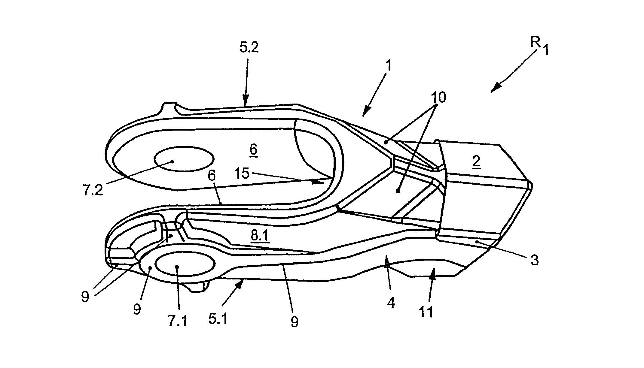
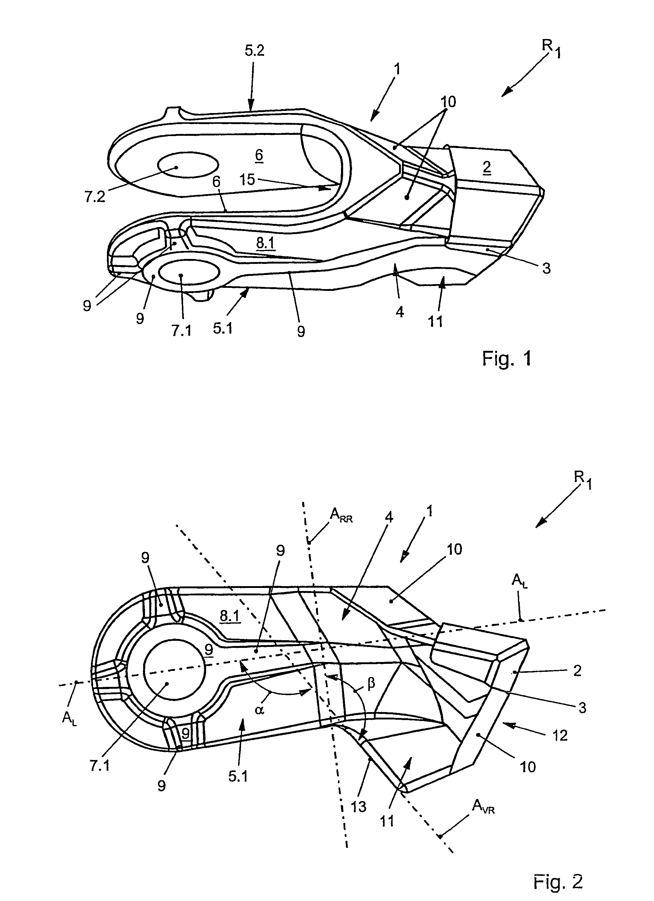
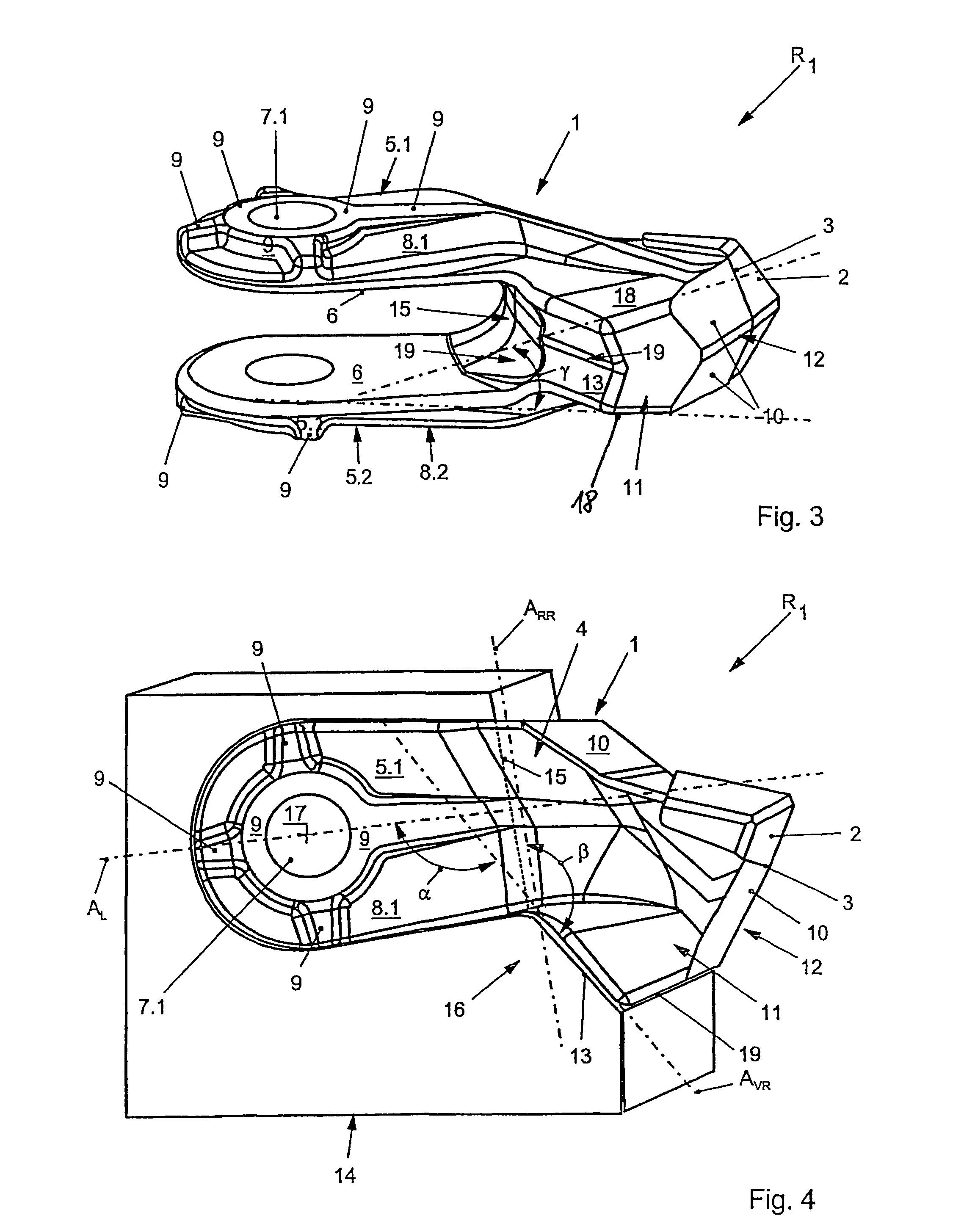
[0024]According to FIG. 1, a cutting element R1 according to the invention has a cutter holder 1 which, in a front region, accommodates at least one cutting edge 2 on a cutter shoulder 3, which cutting edge is connected fixedly or releasably to the cutter holder 1.

[0025]The cutter holder 1 substantially comprises a body part 4 from which two spaced-apart limbs 5.1, 5.2 protrude, with the inner surfaces 6 thereof being formed parallel to each other.

[0026]In the end-side regions of the limbs 5.1, 5.2, the latter have mutually aligned holes 7.1, 7.2.

[0027]It has proven advantageous in the present invention that the two limbs 5.1, 5.2 taper slightly in their thickness from the body part 4 to the hole 7.1, 7.2.

[0028]This enables additional weight and material to be saved, with, in order to compensate for the applied forces, corresponding reinforcing profiles 9 being provided on the outside of an outer surface 8.1, 8.2 of the limbs 5.1, 5.2, said reinforcing profiles reinforcing the regio...


PUM


Abstract

A cutting element for comminuting organic substances, organic materials, soils, plant cultures or the like, in particular for mulching, shredding and chopping, which cutting element can be connected fixedly or releasably to a comminuting rotor.

Description

BACKGROUND OF THE INVENTION[0001]The invention relates to a cutting element for comminuting organic substances, organic materials, soils, plant cultures or the like, in particular for mulching, shredding and chopping, which cutting element can be connected fixedly or releasably to a comminuting rotor.[0002]Cutting elements of this type are frequently placed onto cylindrical rotors in order to form cutting element surfaces for the processing of organic materials, for the processing of soils, for mulching, for shredding, etc.[0003]Conventional cutting elements are subject to a high degree of wear, for example when processing soils or organic cultures.[0004]After a relatively long period of use, and depending on the underlying surface, the cutting elements have to be removed from the rotor and replaced by new ones.[0005]Conventional cutting elements are generally subject to too high a degree of wear, are too expensive to produce and occasionally tend to break off from or deform their h...

Claims


Application Information

Patent Timeline
Patent Type & Authority Patents(United States)
IPC IPC(8): B02C18/18A01F29/09
CPCA01B33/08A01F29/095B02C18/18A01G23/067A01G3/002
Inventor WILLIBALD, ARTUR
Owner AHWI MASCHINENBAU
Why Eureka
Try Eureka