Apparatus for measuring temperature

a technology for measuring apparatus and temperature, applied in the direction of thermometer, using electrical/magnetic means, instruments, etc., can solve the problem of difficult calibration

Active Publication Date: 2012-07-31
EHNDRESS KHAUZER GMBKH KO KG
View PDF17 Cites 6 Cited by
  • Summary
  • Abstract
  • Description
  • Claims
  • Application Information

AI Technical Summary

Benefits of technology

[0003]In view thereof, an object of the invention is to provide a measuring device for measuring and/or monitoring temperature, w

Problems solved by technology

A problem is that these sensors must, over the course of their use, be calibrated after certain intervals of time, as a function of the particular application, in which they are used.
Calibration is difficult to accomplish, since the

Method used


Image

  • Apparatus for measuring temperature
  • Apparatus for measuring temperature

Examples


Embodiment Construction

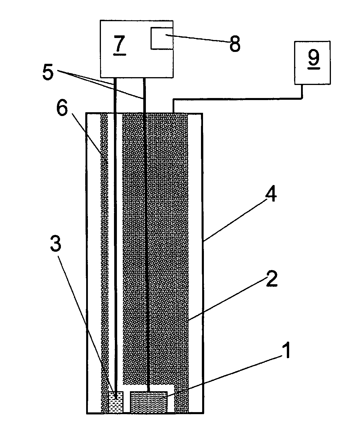
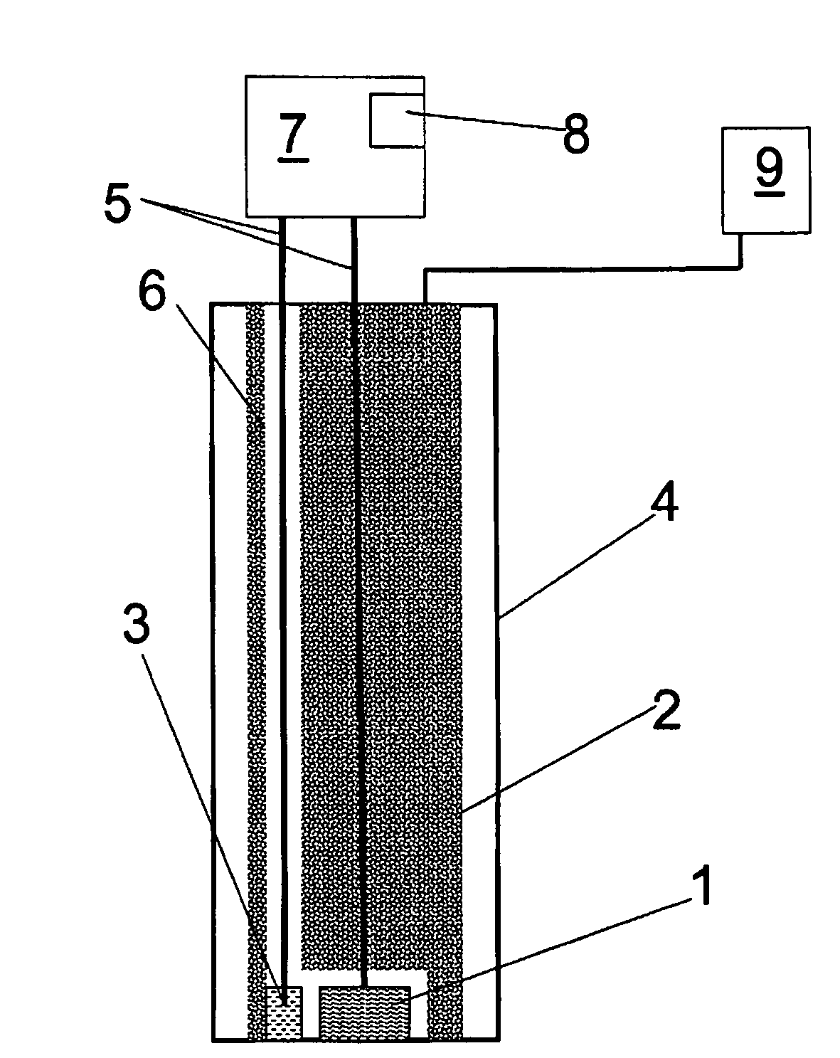
[0021]In FIG. 1, the temperature sensor 1 of the measuring device is accommodated in a housing 4, which is, in this case, a protective tube. In thermal contact with the temperature sensor 1 is a heating / cooling element 2, which is controlled by the control unit 9. The temperatures achieved in this way act also on a reference temperature sensor 3, which can be removed from the housing 4 via the passageway 6 and thus is calibrated on its own and independently of the temperature sensor 1 to be calibrated. Both the temperature sensor 1 and also the reference temperature sensor 3 are connected via electrical connections 5 with a head transmitter 7. The head transmitter receives the measurement data, e.g. the resistance values (when temperature-dependent, resistance elements are being used), and ascertains therefrom the measured temperatures. The measurement data are then stored in a memory unit 8. This arrangement with head transmitter 7 and memory unit 8 can be installed temporarily for...


PUM


Abstract

An apparatus for ascertaining and/or monitoring at least one temperature. The apparatus includes, according to a first variable, at least one temperature sensor, at least one reference temperature sensor and at least one heating/cooling unit, which is thermally coupled with the temperature sensor and with the reference temperature sensor. According to a second variant, the invention includes that at least one reference temperature sensor and the temperature sensor and the reference temperature sensor are embodied and placed in such a manner that they measure essentially the same temperature. At least one head transmitter is provided, which connects the temperature sensor and the reference temperature sensor with the head transmitter in such a manner that the head transmitter receives the data measured by the temperature sensor and the reference temperature sensor. At least one memory unit is provided, in which the measured data of the temperature sensor and the reference temperature sensor are storable.

Description

TECHNICAL FIELD[0001]The invention relates to an apparatus for ascertaining and / or monitoring at least one temperature. The apparatus includes at least one temperature sensor. The temperature can be, for example, that of a medium, such as e.g. a liquid, a bulk good, or a gas. The medium is located in a container or in a tube or pipe.BACKGROUND DISCUSSION[0002]Temperature sensors, or thermometers, are known in the state of the art. A problem is that these sensors must, over the course of their use, be calibrated after certain intervals of time, as a function of the particular application, in which they are used. Calibration is difficult to accomplish, since the temperature sensor is normally installed in a plant, e.g. on a tank or pipe, and must, therefore, be deinstalled for the calibration. This implies, in most cases, that a process being performed must be interrupted. Thus, medium must be drained out of a container, or medium is not permitted to flow through a pipe. Furthermore, ...

Claims


Application Information

Patent Timeline
IPC IPC(8): G01K15/00G01K13/00G01K1/00
CPCG01K15/00
Inventor SCHULZE, STEFAN
Owner EHNDRESS KHAUZER GMBKH KO KG
Why Eureka
Try Eureka