Reduction of flow-induced noise in a centrifugal blower

a centrifugal blower and noise reduction technology, which is applied in the direction of machines/engines, stators, liquid fuel engines, etc., can solve the problems of noise generated by the interaction between the airflow and the smooth inner surface of the blower housing, the noise of extraneous sounds, and the thickening of the inner surface of the blower, so as to achieve efficient airflow transition and effective reduction of flow-induced noise

Active Publication Date: 2012-07-31
WAYNE STATE UNIV
View PDF31 Cites 11 Cited by
  • Summary
  • Abstract
  • Description
  • Claims
  • Application Information

AI Technical Summary

Benefits of technology

[0007]Embodiments of the present invention provide a centrifugal blowing apparatus which effectively reduces flow-induced noise by providing a more efficient transition of airflow through the blower.
[0008]One embodiment of the present invention provides a centrifugal blowing apparatus for reducing flow-induced noise. The apparatus includes a blower housing having a first wall arcuately extending thereabout to define a scroll section formed about a rotational axis. The scroll section includes a circular opening formed therein which defines an inlet configured to draw in air. The scroll section commences with a reduced cross-sectional area at a first end and expands to an increased cross-sectional area at a second end. The reduced cross-sectional area defines a cutoff.
[0010]In another embodiment, a centrifugal blowing apparatus for reducing flow-induced noise is provided. The apparatus includes a blower housing having a first wall arcuately extending thereabout to define a scroll section formed about a rotational axis. The scroll section includes a circular opening formed therein which defines an inlet configured to draw in air. The scroll section commences with a reduced cross-sectional area at a first end and expands to an increased cross-sectional area at a second end. The reduced cross-sectional area defines a cutoff.

Problems solved by technology

One problem with existing blowers is the noise generated by the interaction between the airflow and the smooth inner surface of the blower housing.
However, the presence of skin friction tends to slow down the laminar flow, causing it to grow thicker.
Flow separation noise is a major source of noise generation in the flow-induced sound of a centrifugal blower.
This problem occurs most prominently along the cutoff due to the reduced cross-sectional area of the air passageway within the scroll section.
Thus, the fluid-structure interaction at the cutoff is the major noise source in centrifugal blowers.
Centrifugal blowers are notorious for these extraneous sounds produced while the blower is in operation.
Many people find these sounds to be unpleasant and annoying.

Method used


Image

  • Reduction of flow-induced noise in a centrifugal blower
  • Reduction of flow-induced noise in a centrifugal blower
  • Reduction of flow-induced noise in a centrifugal blower

Examples


Embodiment Construction

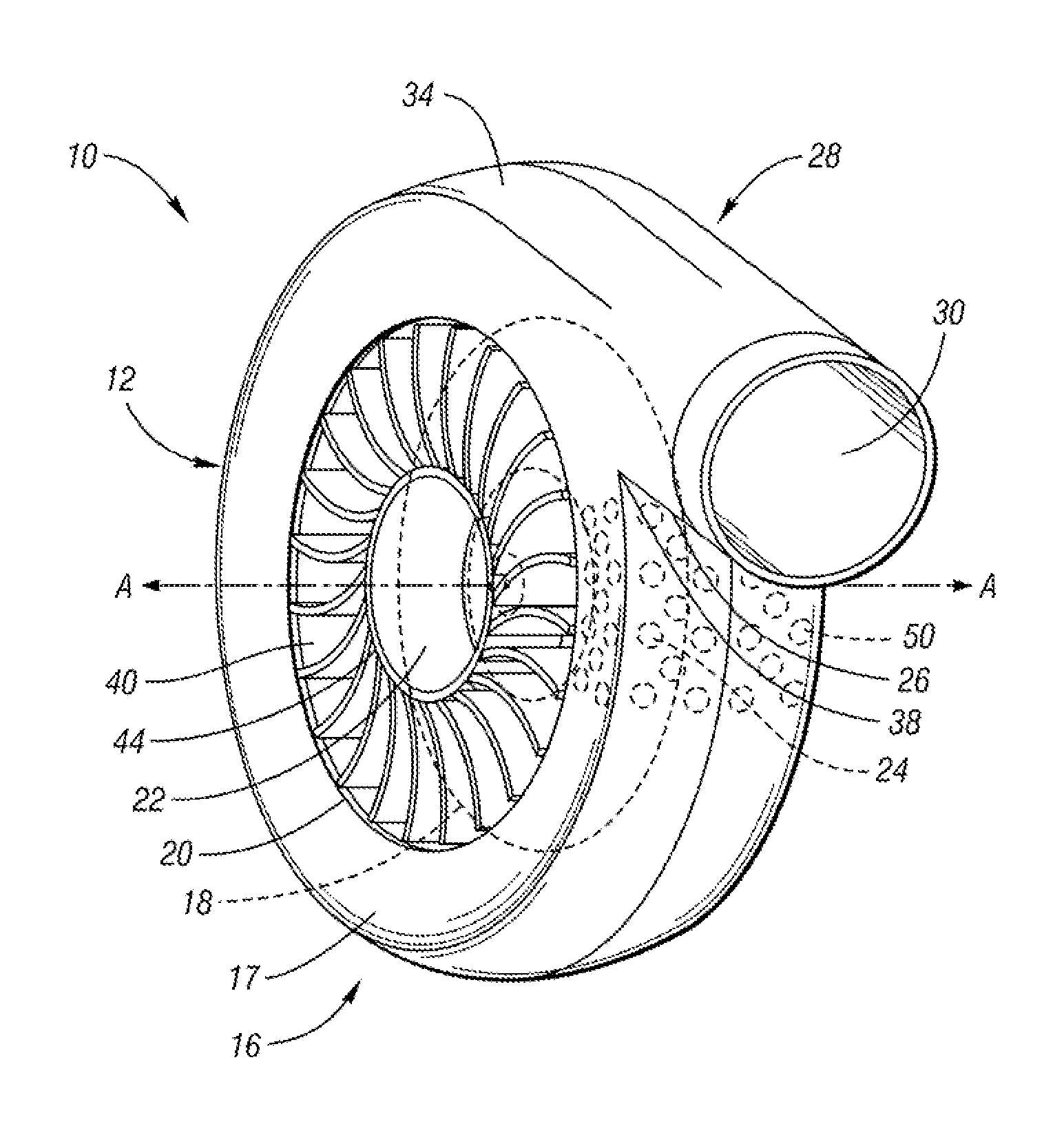
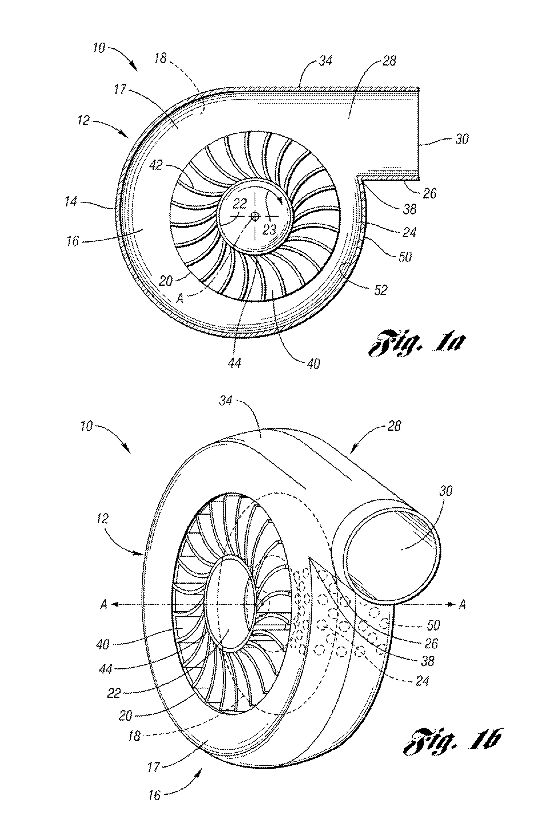
[0020]The present invention generally provides a centrifugal blower having reduced noise generation. The blower includes a distinct surface roughness along an inner surface of a scroll-housing at a cutoff defined by a reduced airflow cross-sectional area within the scroll-housing. The unique surface roughness at the cutoff effectively reduces flow-induced noise by providing an efficient transition of airflow through the blower.

[0021]FIGS. 1a-b illustrate a centrifugal blower 10 constructed in accordance with one embodiment of the present invention. As shown, the blower 10 generally includes a scroll-shaped blower housing 12 formed of first and second sidewalls 17, 18 spaced apart by a scroll wall 14. In this embodiment, the scroll wall 14 arcuately extends about a rotational axis A to define a circular scroll section 16. The scroll section 16 includes a circular opening20 formed therein through sidewalls 17, 18. The opening 20 defines an inlet 22 configured to draw in air. The blowe...


PUM


Abstract

A centrifugal blowing apparatus for reducing flow-induced noise is disclosed. The apparatus includes a blower housing having a scroll section formed about a rotational axis and an exhaust section extending from the scroll section. The scroll section includes an opening defining an inlet configured to draw in air and the exhaust section defines an outlet in fluid communication with the inlet. The scroll section commences with a reduced cross-sectional area defining a cutoff and expands to an increased cross-sectional area. An impeller is disposed in the opening of the scroll section about the rotational axis and includes an outer surface having impeller blades radially disposed thereon. The impeller blades rotate to direct a flow of air from the inlet through the scroll section to the outlet. A plurality of indentations is formed along an inner surface of the scroll section at the cutoff.

Description

BACKGROUND[0001]1. Field of the Invention[0002]The present invention generally relates to centrifugal blowers. More particularly, the invention relates to a centrifugal blower having reduced noise generation.[0003]2. Description of Related Art[0004]Centrifugal fans or blowers, also known as scroll-type blowers, are utilized in a wide variety of applications where efficient movement of air is required, including HVAC systems for automobiles and office buildings.[0005]One problem with existing blowers is the noise generated by the interaction between the airflow and the smooth inner surface of the blower housing. As air flows over the smooth surface, a thin boundary layer is formed which tends to adhere to the surface, due to viscosity, and flows smoothly over the surface, known as laminar flow. However, the presence of skin friction tends to slow down the laminar flow, causing it to grow thicker. Eventually, separation occurs and the flow becomes turbulent. As a consequence of this f...

Claims


Application Information

Patent Timeline
Patent Type & Authority Patents(United States)
IPC IPC(8): F04D29/66
CPCF04D29/4226F04D29/661F04D29/422
Inventor WU, SEAN F.
Owner WAYNE STATE UNIV
Why Eureka
Try Eureka